Punching apparatus

A stamping device and stamping tool technology, applied in the direction of piercing presses, metal processing equipment, piercing tools, etc., can solve the problems of complex transmission mechanism, high size and cost

Active Publication Date: 2017-04-19
SALVAGNINI ITAL
View PDF6 Cites 4 Cited by
  • Summary
  • Abstract
  • Description
  • Claims
  • Application Information

AI Technical Summary

Problems solved by technology

[0014] A disadvantage of existing multi-tool punching devices with fixed or rotating punches, with a single tool holder arrangement or with multiple tool holder arrangements (multiple punches) is that they require three separate actuators for for moving the ram and for selecting and angularly orienting the punching tool
The three actuators and the corresponding transmission mechanisms are usually complex, with associated dimensions and high costs

Method used


Image

  • Punching apparatus
  • Punching apparatus
  • Punching apparatus

Examples


Embodiment Construction

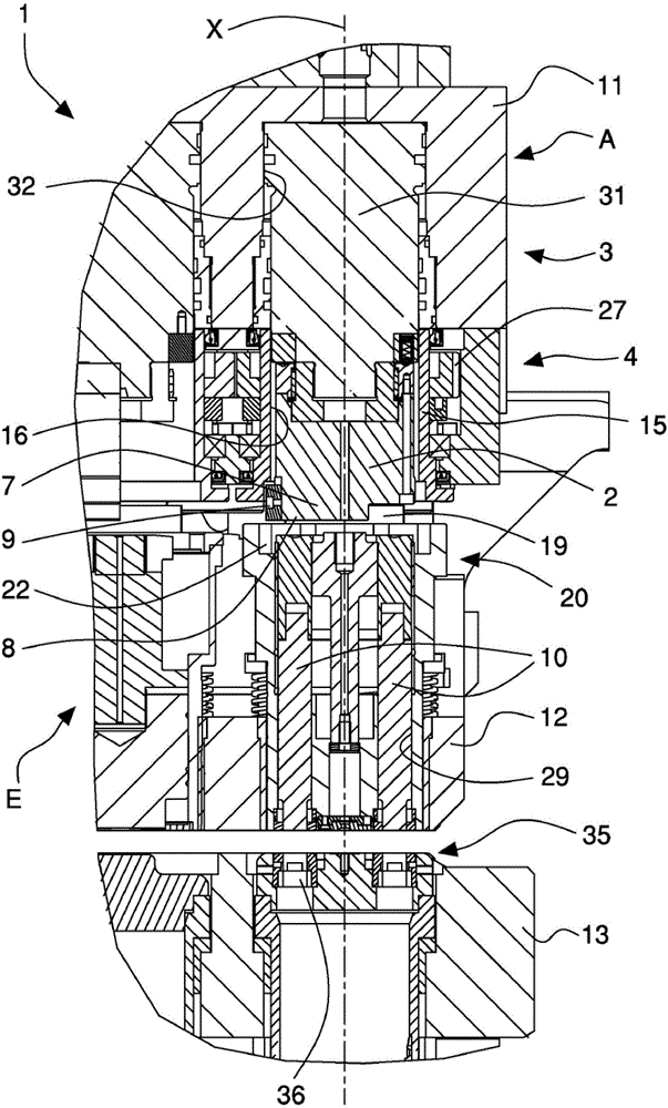
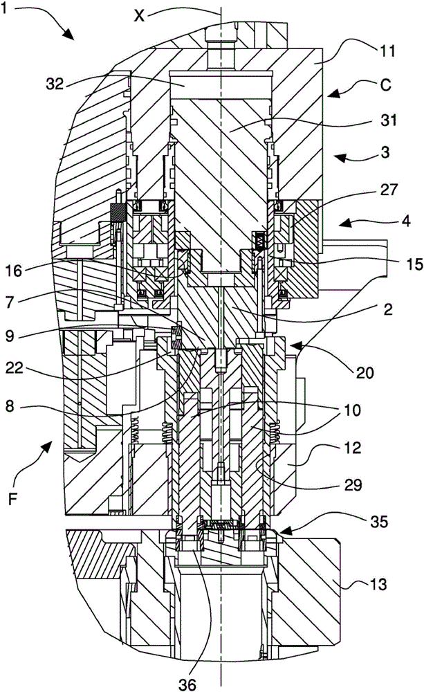
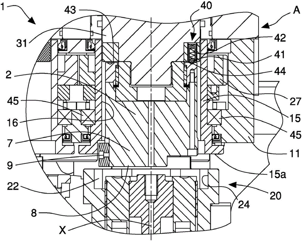
[0027] refer to Figure 1 to Figure 6 , shows a punching device 1 according to the invention, which may be associated with a punching machine tool of known type, not shown, arranged to perform cutting and / or punching on workpieces, in particular on sheet metal. / or stamping.

[0028] The stamping device 1 , usually also called a stamping head, comprises a tool holder 20 , a striking element 2 called a ram, a first drive mechanism 3 and a second drive mechanism 4 , wherein the tool holder 20 is provided with multiple a punching tool 10, the striking element 2 is adapted to interact with and selectively drive a set punching tool 10 (referred to as a punch), said first drive mechanism 3 for The striking element 2 is moved, and the second drive mechanism 4 is used to move the tool holder unit 20 .

[0029] The tool holder unit 20 generally comprises a drum, rotatable about a working axis X, and provided with a plurality of sockets 21 adapted to slidably receive a respective pun...


PUM


Abstract

A punching apparatus comprises a tool holder unit (20) rotatable around a working axis (X) and provided with a plurality of seats (21) suitable for slidably housing respective punching tools (10), a beating element (2) movable along and around the working axis (X) and provided with an operating end (7) having a beating portion (8), to selectively interact with a set punching tool (10), first driving means (3) for moving the beating element (2) along the working axis (X) so as to move set punching tool (10) and second driving means (4) for rotating the tool holder unit (20) around the working axis (X); the operating end (7) of the beating element (2) comprises a first coupling element (9) and the tool holder unit (20) comprises a plurality of second coupling elements (22) each of which is associated with a respective seat (21) and arranged to couple with the first coupling element (9) in a connection configuration (F) in which the beating element (2) and the tool holder unit (20) are coupled and rigidly rotate; the second driving means (4) in a selection configuration (E) rotates the tool holder unit (20) for positioning the set punching tool (10) so that the latter faces the beating portion (8) of the operating end (7) and allows the first coupling element (9) to couple with the second coupling element (22) that is associated with the seat (21) of the set punching tool (10) and, in the connection configuration (F), rotates the tool holder unit (20) and the beating element (2) which are mutually connected for angularly orienting the set punching tool (10).

Description

technical field [0001] The invention relates to machine tools for machining workpieces and / or sheet metal, and in particular to a punching device associated with a punching machine for performing cutting and / or punching. Background technique [0002] Known punching machines are provided with a punching device called a punching head, which supports and moves a punching tool along a working axis, which punching tool acts on a workpiece, usually a sheet metal, It cooperates with the lower punching die or counter-punch. Typically, the die is fixed to the table of the punching machine, which supports the workpiece to be machined. [0003] In stamping heads with a single tool, the latter, ie the single tool, is mounted on a support element (a so-called mandrel) which is driven linearly along and around the working axis by means of a corresponding actuator driven in rotation. Linear movements in two opposite directions along the working axis allow to carry out the working stroke...

Claims


Application Information

Patent Timeline
Patent Type & Authority Applications(China)
IPC IPC(8): B21D28/12B21D28/24
CPCB21D28/125B21D28/246B21D28/34B21D28/36B21J9/04
Inventor N·梅内盖蒂
Owner SALVAGNINI ITAL
Why Eureka
Try Eureka