
Dental chair

A technology for dental chairs and base plates, applied in dental chairs, dentistry, operating chairs, etc., can solve the problems of inconvenient adjustment, complex structure of dental chairs, and not easy to carry, etc., and achieve the effect of simple structure, easy portability, and convenient adjustment

Inactive Publication Date: 2017-04-26
CHENGDU XUNDE SCI & TECH
View PDF5 Cites 7 Cited by
  • Summary
  • Abstract
  • Description
  • Claims
  • Application Information

AI Technical Summary

Problems solved by technology

[0003] The existing dental chair has a complex structure, is not easy to carry, and is inconvenient to adjust

Method used


Image

  • Dental chair
  • Dental chair
  • Dental chair

Examples


Embodiment Construction

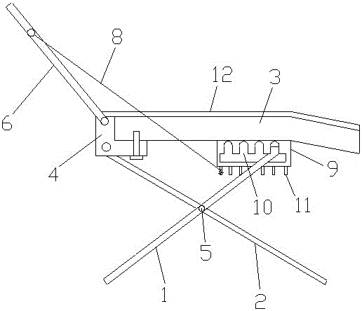
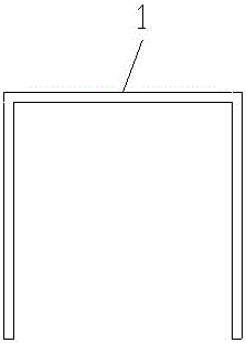
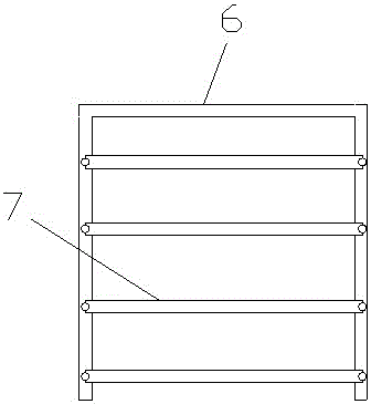
[0014] Such as Figure 1-Figure 3 As shown, a dental chair includes a U-shaped first strut 1, two second struts 2, a base plate 3 and two supports 4, and the middle part of the first strut 1 is connected to the two second struts respectively. The middle part of the pole 2 is connected by a rotating shaft 5, and the two supports 4 are fixedly connected to both sides of one end of the bottom plate 3, and the top of the second pole 2 is movably connected with the support 4, and the second support can be passed through the second support by installing the rotating shaft. Rod 2 and support 4, so that the two can be flexibly connected, said support 4 is movably connected with a U-shaped gear lever 6, said gear lever 6 is evenly distributed with nylon braid 7, nylon rope braid 7 The two ends are fixed on both ends of the gear bar 6 by rivets, the rivets run through the nylon rope braid 7 and the gear bar 6, the nylon ropes 8 are fixed on both sides of the gear bar 6, and the mounting...


PUM


Abstract

The invention discloses a dental chair. The dental chair comprises a U-shaped first support rod, two second support rods, a bottom plate and two support seats. The middle part of the first support rod is connected with middles of the two second support rods through a rotary shaft. The two support seats are fixedly connected to two sides of one end of a bottom plate. Tops of the second support rods are movably connected with the support seats. The support seats are movably connected with U-shaped blocking rods, on which nylon woven belts are uniformly distributed. Two sides of each blocking rod are fixed with nylon ropes. Two sides of the bottom plate are welded with installing plates, in which multiple clamping grooves with arc tops are uniformly distributed. The bottoms of the installing plates are welded with multiple cylindrical pins distributed at equal intervals. The dental chair is simple in structure, and convenient to carry and adjust.

Description

technical field [0001] The present invention relates to a dental chair. Background technique [0002] The dental chair is mainly used for the examination and treatment of oral surgery and oral diseases. At present, electric dental chairs are mostly used, and its main structure is divided into 8 parts ( figure 1 ), the whole machine base plate is fixed on the ground, and the base plate is connected with the upper part of the dental chair through the bracket. The action of the dental chair is controlled by the control switch on the back of the chair. Its working principle is: the control switch starts the motor to run and drives the transmission mechanism Work to make the corresponding parts of the dental chair move. According to the needs of treatment, manipulate the control switch button, the dental chair can complete actions such as rising, falling, bending, supine position and reset. It is mainly used for the examination and treatment of oral surgery and oral diseases. ...

Claims


Application Information

Patent Timeline
Patent Type & Authority Applications(China)
IPC IPC(8): A61G15/04A61G15/10
CPCA61G15/02A61G15/10A61G2203/70
Inventor 龚素华
Owner CHENGDU XUNDE SCI & TECH
Learn More