
Detection system and micro-fluidic chip clamp therefor

A technology of microfluidic chips and fixtures, applied in the direction of supporting appliances, laboratory appliances, chemical instruments and methods, etc., can solve the problems of irreversible connection methods, inconvenient chip installation and disassembly, inconvenient use, etc., to achieve opening and closing The effect of easy state, easy installation and removal, easy use and management

Active Publication Date: 2017-04-26
GUANGDONG SHUNDE IND DESIGN INST GUANGDONG SHUNDE INNOVATIVE DESIGN INST
View PDF9 Cites 16 Cited by
  • Summary
  • Abstract
  • Description
  • Claims
  • Application Information

AI Technical Summary

Problems solved by technology

Since the microfluidic chip used for digital PCR detection devices generally only arranges the diluent, when the droplet size is smaller than the channel size of the chip, the arrangement effect is poor, so the chip is often replaced due to the change of the droplet size
When the microfluidic chip is installed, it needs to be connected with the external pump valve system and pipeline. At present, the microfluidic chip and the pipeline are connected by pins, glue, etc., but these connection methods are irreversible and cannot be connected to the chip. Replacement; there is also a connection method to fix the microfluidic chip through a fixture, but when replacing the chip, all the fixture parts need to be dismantled, which is inconvenient for chip installation and disassembly, inconvenient to use, and reduces detection efficiency

Method used


Image

  • Detection system and micro-fluidic chip clamp therefor
  • Detection system and micro-fluidic chip clamp therefor
  • Detection system and micro-fluidic chip clamp therefor

Examples


Embodiment Construction

[0024] Embodiments of the present invention are described in detail below in conjunction with accompanying drawings:

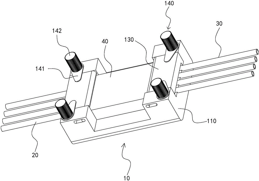
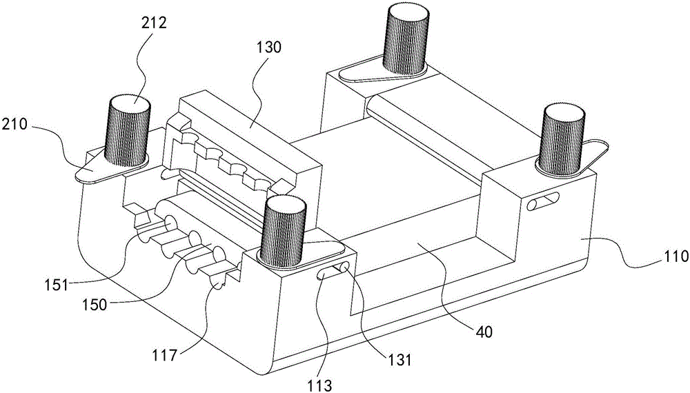
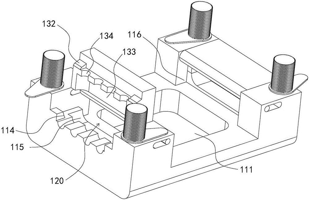
[0025] like Figure 1 to Figure 3 As shown, a detection system includes a microfluidic chip holder 10, a liquid inlet conduit 20, and a liquid outlet conduit 30. The microfluidic chip holder 10 includes a base 110, two flip covers 130 that are rotatably connected to the base 10, and the The flip cover 130 is fixed on the fastening mechanism 140 on the base 10. Each flip cover 130 cooperates with the base 10 to form a clamping space 120. The base 10 is provided with a chip slot 111 for placing the microfluidic chip 40. The chip slot 111 and the two Two clamping spaces 120 communicate, and one end of the microfluidic chip 40 with a liquid inlet extends into one of the clamping spaces 120, and is docked with the liquid inlet conduit 20, and one end of the microfluidic chip 40 with a liquid outlet extends into the other. The space 120 is clamped and connected to ...


PUM


Abstract

The invention relates to a detection system and a micro-fluidic chip clamp therefor. The micro-fluidic chip clamp comprises a base, two turning covers which are both rotationally connected with the base and matched with the base to form clamping spaces, and a fastening mechanism for fixing the turning covers on the base, wherein a chip groove for placing a micro-fluidic chip is formed in the base; the chip groove is connected with the two clamping spaces; one end, equipped with a liquid inlet, of the micro-fluidic chip extends into one clamping space while one end, equipped with a liquid outlet, of the micro-fluidic chip extends into the other clamping space; and the micro-fluidic chip is clamped between the two turning covers. When the micro-fluidic chip is installed, the fastening mechanism is opened, and the turning covers are turned up, and then the micro-fluidic chip is placed in the chip groove, the turning coves are closed, and the fastening mechanism is tightly locked; and when the micro-fluidic chip needs to be replaced, the fastening mechanism is opened, the turning coves are turned up, the original micro-fluidic chip is taken out and a new micro-fluidic chip is placed into the chip groove, so that the replacement of the micro-fluidic chip is quite convenient, and the detection efficiency is improved.

Description

technical field [0001] The invention relates to the technical field of microfluidic chips, in particular to a detection system and a microfluidic chip fixture thereof. Background technique [0002] The digital PCR (Polymerase chain reaction) detection device requires high detection accuracy and needs to be able to accurately detect the size of the fluorescent signal contained in each liquid droplet passing through the detection flow channel. Evenly spaced. Since the microfluidic chip used for digital PCR detection devices generally only arranges the diluent, when the droplet size is smaller than the channel size of the chip, the arrangement effect is poor, so the chip is often replaced due to the change of the droplet size. When the microfluidic chip is installed, it needs to be connected with the external pump valve system and pipeline. At present, the microfluidic chip and the pipeline are connected by pins, glue, etc., but these connection methods are irreversible and ca...

Claims


Application Information

Patent Timeline
IPC IPC(8): B01L9/00
CPCB01L9/527B01L2200/12
Inventor 李冬梅李晶陈庆明任晓龙
Owner GUANGDONG SHUNDE IND DESIGN INST GUANGDONG SHUNDE INNOVATIVE DESIGN INST
Learn More