A punching device for chamfering the inner wall of a hole

A technology of hole inner wall and chamfering, applied in the structural design and application field of china, can solve the problems of chamfering deflection of three holes in the shell cavity and so on.

Active Publication Date: 2018-10-02
沈阳兴华航空电器有限责任公司
View PDF7 Cites 1 Cited by
  • Summary
  • Abstract
  • Description
  • Claims
  • Application Information

AI Technical Summary

Problems solved by technology

Solve the problem of chamfer deflection in the three holes of the shell cavity and the riveting problem caused by it

Method used


Image

  • A punching device for chamfering the inner wall of a hole
  • A punching device for chamfering the inner wall of a hole
  • A punching device for chamfering the inner wall of a hole

Examples


Embodiment 1

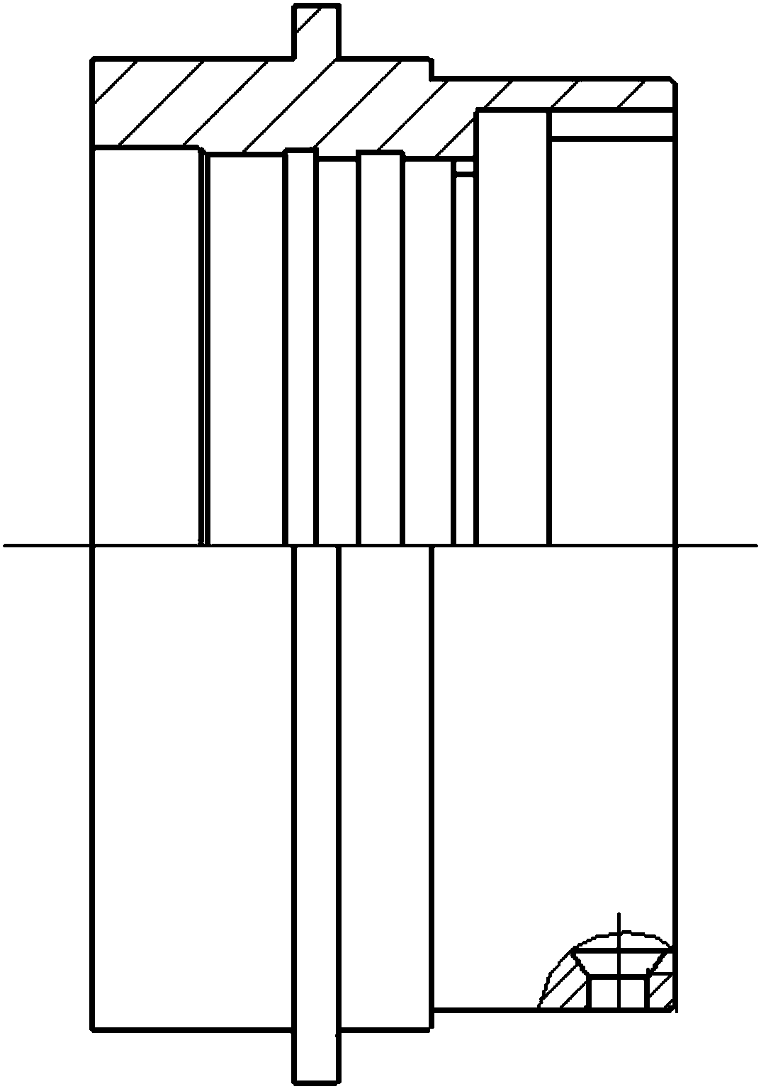
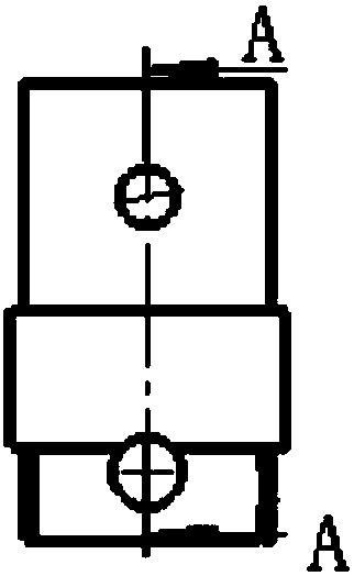
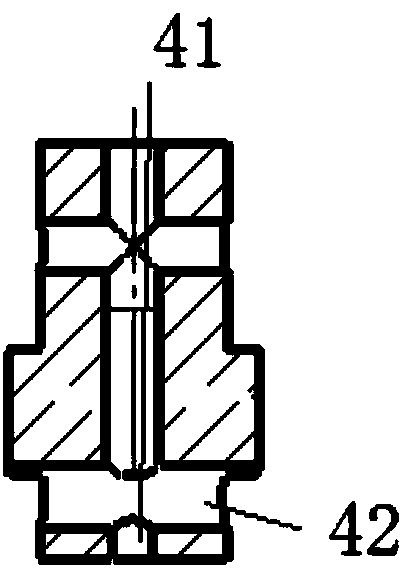
[0023] The punching device for chamfering the inner wall of the hole is composed as follows: lower fixing plate 1, inserting plate 2, lower punch 3, pillar 4, first pin 5, upper fixing plate 6, upper punch 7, second pin 8. Bolt 9, third pin 10 and guide post 11; wherein, the pillar 4 is a columnar structure with an asymmetrical ellipse in cross-section, and the two semi-arc contact ends of the asymmetrical ellipse have R5 chamfering structure 43, and the asymmetrical ellipse The half-arc on one side can be positioned and contacted with the inner diameter of the punched part, and the form of the R5 chamfering structure 43 at the two half-arc contact ends of the asymmetric ellipse ensures that the part can be inserted and taken out smoothly. The pillar 4 includes an axial stepped through hole 41 and a first radial through hole 42, the axial stepped through hole 41 and the first radial through hole 42 communicate through each other, and one end of the lower punch 3 is chamfered wi...


PUM


Abstract

The invention discloses a punching device for chamfering the inner wall of a hole. The punching device for chamfering the inner wall of a hole is composed as follows: a lower fixing plate (1), an inserting plate (2), a lower punch (3), a pillar ( 4), the first pin (5), the upper fixing plate (6), the upper punch (7), the second pin (8), the bolt (9), the third pin (10) and the guide post (11 ); wherein, the pillar (4) is a columnar structure with an asymmetrical ellipse in cross-section, and the two semi-arc contact ends of the asymmetrical ellipse have R5 chamfering structures (43), and the chamfering and punching device on the inner wall of the hole solves the problem of Solving the problem of inner chamfer deflection caused by the old fitter drilling process is especially important for ensuring the processing quality of the inner chamfer of the part, meeting the riveting force requirements of the bayonet pin, and improving the quality stability of the product. For other similar parts structures It has important application value in processing.

Description

technical field [0001] The invention relates to the technical field of structural design and application of a chamfering punching device, and in particular provides a chamfering punching device for the inner wall of a hole. Background technique [0002] A large number of housings in the connector exist in the processing technology of the inner chamfering of the three horizontal holes of the housing cavity. For details, refer to the attached figure 1 , due to the limited space on the inner wall, the chamfering process is performed by drilling, so that the chamfering is deflected. The smaller the shell hole, the larger the deflection angle. Especially when the chamfered part is used for riveting bayonet pins, the deflection of the chamfered corners will easily lead to unreliable riveting, unqualified riveting force, and hidden quality problems. [0003] People urgently hope to obtain a kind of hole inner wall side chamfer punching device with excellent technical effect. Con...

Claims


Application Information

Patent Timeline
Patent Type & Authority Patents(China)
IPC IPC(8): B21D19/08B21D43/00
CPCB21D19/08B21D43/003
Inventor 庞金红南艳明高成刚包望
Owner 沈阳兴华航空电器有限责任公司
Why Eureka
Try Eureka