A high-speed parallel robot mechanism capable of scara motion
A robot and high-speed technology, applied in the direction of manipulators, program-controlled manipulators, manufacturing tools, etc., can solve the problems of unfavorable mechanism dynamic response characteristics, easy to generate vibration, etc., and achieve improved stiffness and dynamic response characteristics, compact structure, clear movement mode Effect
- Summary
- Abstract
- Description
- Claims
- Application Information
AI Technical Summary
Problems solved by technology
Method used
Image
Examples
Embodiment 1
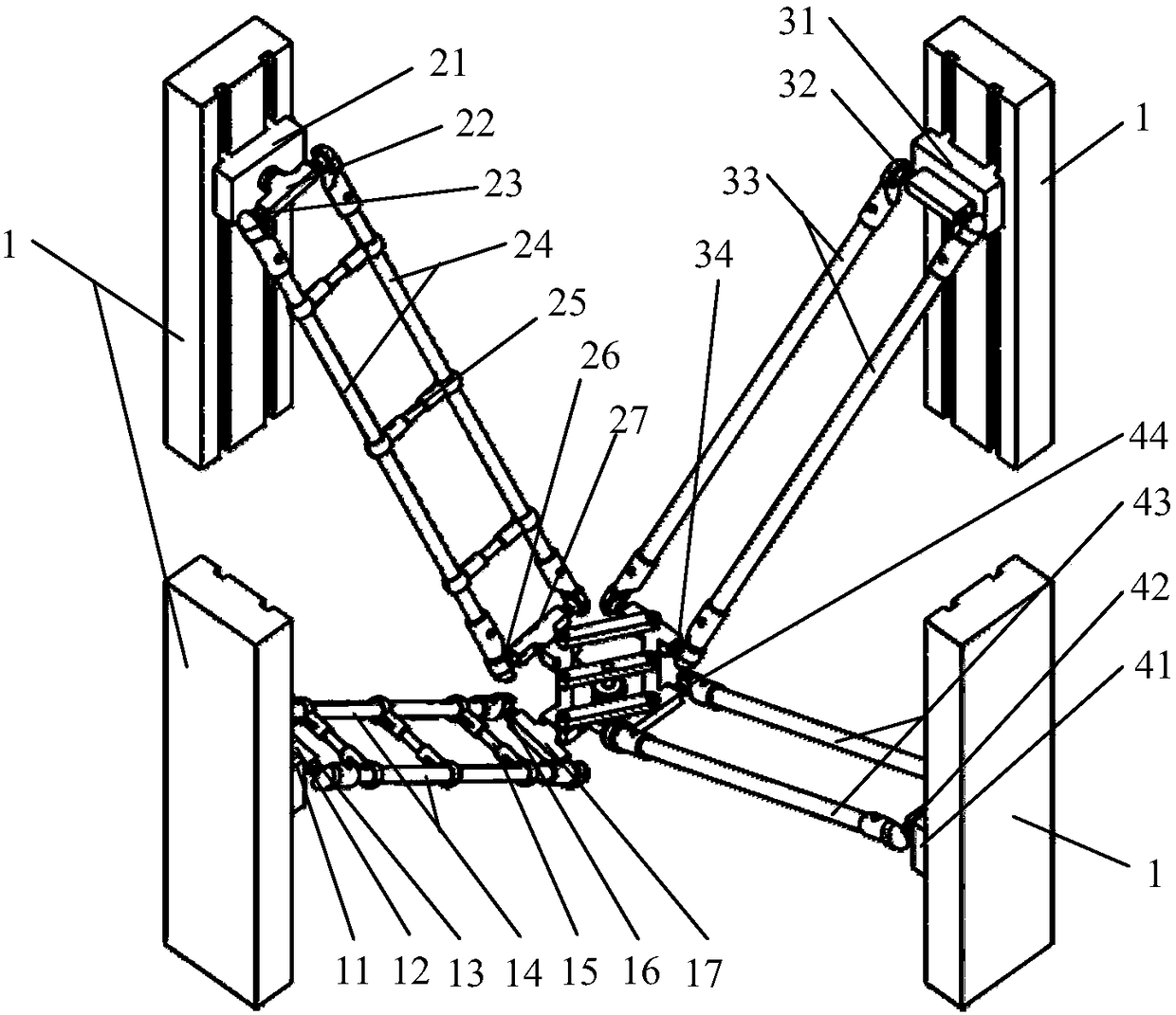
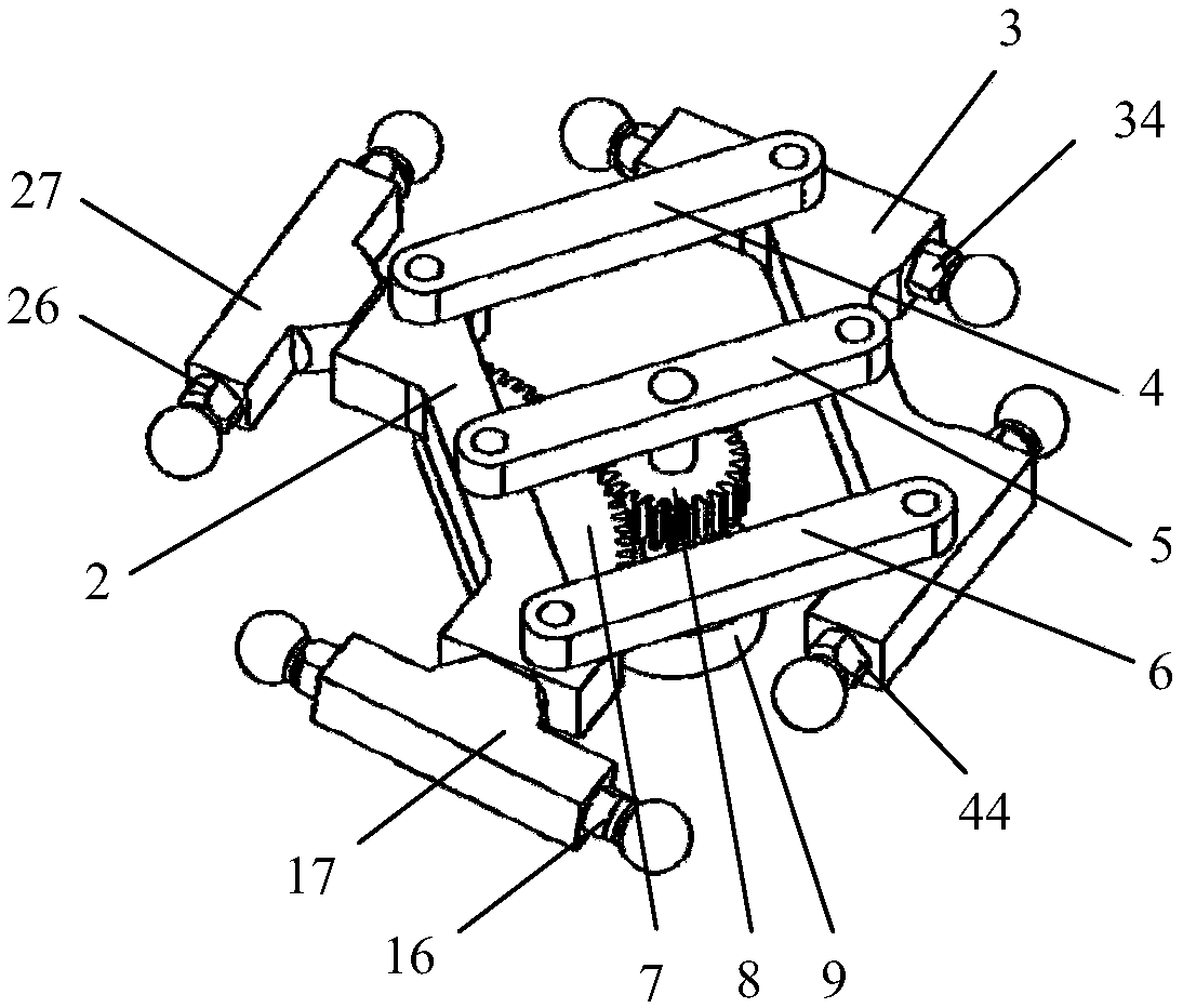
[0030] combine Figure 1-2 , a high-speed parallel robot mechanism that can realize SCARA motion, including a fixed frame 1, a moving platform, and a first branch chain, a second branch chain, a third branch chain and a fourth branch chain arranged between the fixed frame 1 and the moving platform chain, the first branch chain is adjacent to the second branch chain and has the same structure, and the third branch chain and the fourth branch chain are adjacent and have the same structure;
[0031] The first branch chain includes a first slide plate 11, a first rotation axis A12, a first upper connecting shaft 13, two parallel and equal-length first distant frame rods 14, a first support rod 15, and a first lower connecting shaft 16 and the first rotating shaft B17; the first sliding plate 11 is connected with the fixed frame 1 through a moving pair, the first rotating shaft A12 is rotationally connected with the first sliding plate 11, and one end of the first far frame rod 14 ...
Embodiment 2
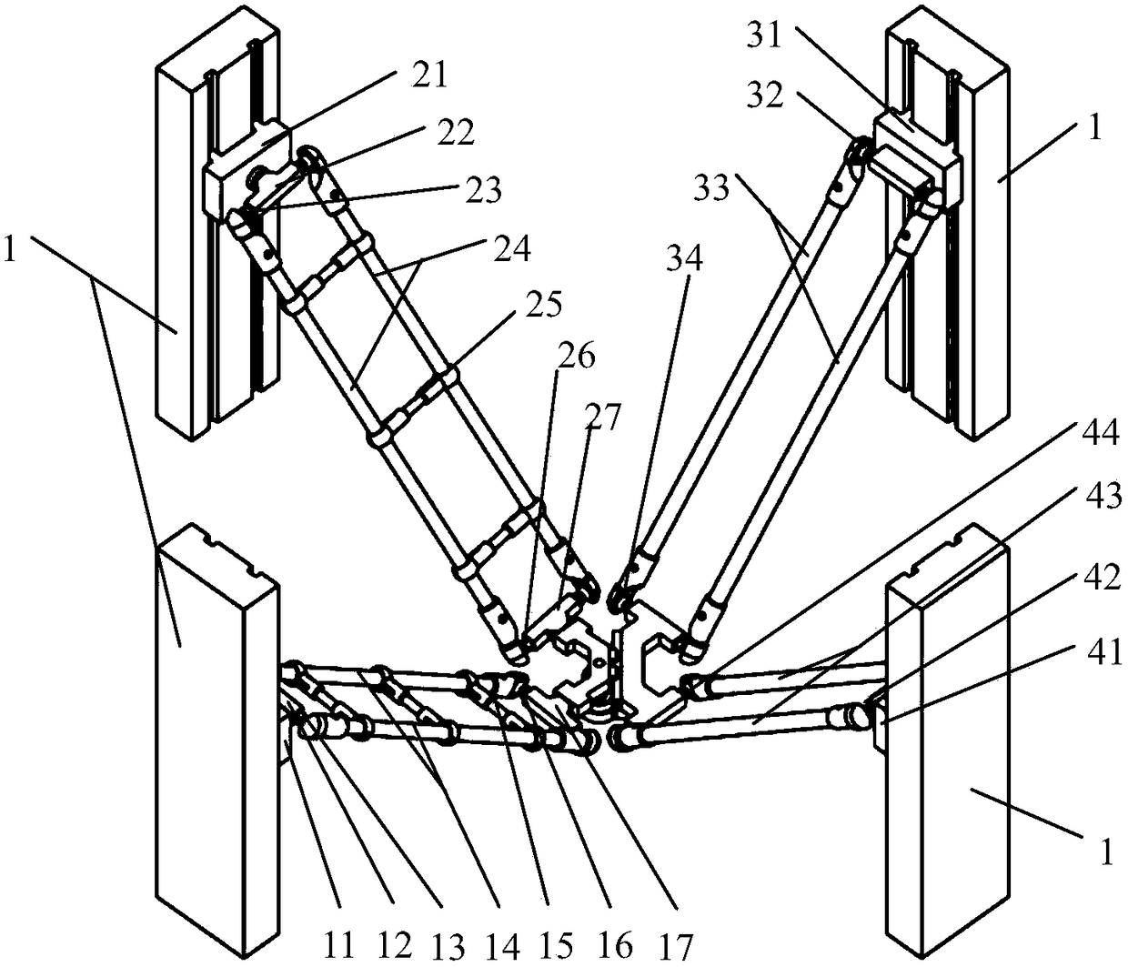
[0041] combine Figure 3-4 , this embodiment is similar to Embodiment 1, the only difference is that: the main platform 2 and the auxiliary platform 3 are connected by guide rail sliders, the main platform 2 is fixedly connected with a slider 102, and the auxiliary platform 3 is A guide rail 101 is affixed, and the guide rail 101 and the slider 102 form a guide rail slider pair; the main platform 2 is rotatably connected with a pinion 8-1, and the auxiliary platform 3 is affixed with a rack 10. The pinion 8-1 meshes with the rack 10; the lower end of the pinion 8-1 is fixedly connected with an end effector 9.
Embodiment 3
[0043] combine Figure 1-2 , this embodiment is similar to Embodiment 1, the only difference is that the pinion 8 is arranged on the first connecting rod 4 .
PUM
 Abstract
Description
Claims
Application Information
 - R&D
- Intellectual Property
- Life Sciences
- Materials
- Tech Scout
- Unparalleled Data Quality
- Higher Quality Content
- 60% Fewer Hallucinations
Browse by: Latest US Patents, China's latest patents, Technical Efficacy Thesaurus, Application Domain, Technology Topic, Popular Technical Reports.
© 2025 PatSnap. All rights reserved.Legal|Privacy policy|Modern Slavery Act Transparency Statement|Sitemap|About US| Contact US: help@patsnap.com


