Bidirectional trough type conveyor

A technology of trough conveyors and troughs, which is applied in the direction of conveyors, conveyor objects, transportation and packaging, etc., to achieve the effect of a good sealing state

Inactive Publication Date: 2017-04-26
SINOMA SHANGRAO MACHINERY LIMITED
View PDF5 Cites 8 Cited by
  • Summary
  • Abstract
  • Description
  • Claims
  • Application Information

AI Technical Summary

Problems solved by technology

For example, the feeding point is between two storage warehouses, and the equipment is required to feed materials to the two storage warehouses separately. In this case, only two conveyors can be used to solve the material transportation problem

Method used


Image

  • Bidirectional trough type conveyor
  • Bidirectional trough type conveyor
  • Bidirectional trough type conveyor

Examples


Embodiment Construction

[0016] The present invention will be further described below in conjunction with the accompanying drawings of the embodiments.

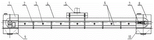
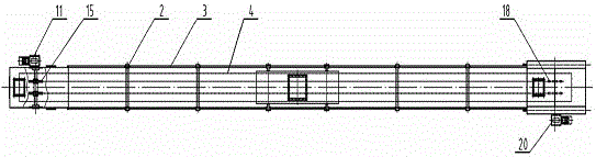
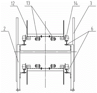
[0017] As shown in the figure, at both ends of the bracket 2 are provided a head device 1 composed of a drive sprocket set and a tail device 8 composed of a reversing sprocket set. The head device 1 and the tail device 8 are respectively provided with a head The bottom discharge port 9 and the tail discharge port 10; the support 2 is provided with an upper and lower double-layer track 6, and a trough 12 is provided on the track 6, and the bottom of the trough 12 is provided with rollers 14 on both sides to cooperate with the track 6, and the bottom of the trough 12 Two chains 13 are also provided to cooperate with the driving sprocket 15 of the head device 1 and the reversing sprocket 18 of the tail device; the support 2 is provided with a feed port 5 with a dust cover, and the feed port 5 is in the trough 12 Above.

[0018] The running part 4 (including...


PUM


Abstract

The invention relates to a bidirectional trough type conveyor. A head device composed of a drive chain wheel set and a tail device composed of a reversing chain wheel set are arranged at the two ends of a support of the conveyor correspondingly, and a head discharging opening and a tail discharging opening are formed below the head device and the tail device correspondingly. An upper-layer rail and a lower-layer rail are arranged on the support. Troughs are arranged on the rails. Rolling wheels are arranged on the two sides of the bottom of each trough and cooperate with the corresponding rail. Two chains are further arranged at the bottom of each trough and cooperate with a drive chain wheel of the head device and a reversing chain wheel of the tail device. A feeding opening with a dustproof cover is formed in the support, and the feeding opening is located above the troughs. A transmission device is connected to one side of the head device. The bidirectional trough type conveyor operates bidirectionally and can achieve multi-point feeding and two-end discharging.

Description

Technical field [0001] The invention relates to a conveyor, in particular to a two-way trough conveyor. Background technique [0002] Trough conveyor is a continuous conveying equipment for conveying bulk materials. The chain of the running part of the equipment moves from the tail to the head under the traction of the rotating sprocket at the head. When it passes the head, it turns to the tail, and then it passes the tail sprocket and turns to the head to form a closed and continuous conveyor loop. . The upper chute of the conveying ring is loaded with materials, and the lower layer is the return section of the running part. The feeding point can be set at multiple points between the head and the tail, and the discharge point is set at the lower end of the head. In order to prevent material leakage during the conveying process, better sealing between the troughs is required. For this reason, the mounting of the troughs is directional, so the conveyor can only run in one direct...

Claims


Application Information

Patent Timeline
Patent Type & Authority Applications(China)
IPC IPC(8): B65G17/12B65G17/36B65G17/42B65G23/06B65G17/30B65G47/44B65G47/38
CPCB65G17/123B65G17/30B65G17/36B65G17/42B65G23/06B65G47/38B65G47/44B65G2201/04
Inventor 周敏虎黄发义杨自成林志祥张才仙张光伟张结元钱丽丽徐珊叶锟
Owner SINOMA SHANGRAO MACHINERY LIMITED
Why Eureka
Try Eureka