An integrated wire outlet and guide wire mechanism and a steel bar binding machine

An integrated, guide wire technology, which is applied in building construction, building material processing, construction, etc., can solve the problems of installation position deviation, steel wire cannot protrude from the guide, and unstable circle size, etc.

Active Publication Date: 2019-03-01
TAIZHOU XINDALU ELECTRONICS TECH
View PDF9 Cites 4 Cited by
  • Summary
  • Abstract
  • Description
  • Claims
  • Application Information

AI Technical Summary

Problems solved by technology

[0004] In the prior art, the guide mechanism of the steel bar binding machine has a large number of components and cumbersome processing, and the processing of multiple parts separately may easily cause the accumulation of part processing size errors, and the deviation of the installation position may easily occur during the installation process, resulting in the formation of steel wires. When it is round, the size of the circle is unstable or the steel wire cannot protrude from the guide. The invention provides an integrated wire guide wire mechanism and a steel bar binding machine. Accumulation of dimensional errors in parts processing and deviation of installation position during installation, so that the steel wire can be stretched out smoothly, and the round size of the steel wire is stable

Method used


Image

  • An integrated wire outlet and guide wire mechanism and a steel bar binding machine
  • An integrated wire outlet and guide wire mechanism and a steel bar binding machine
  • An integrated wire outlet and guide wire mechanism and a steel bar binding machine

Examples


Embodiment 1

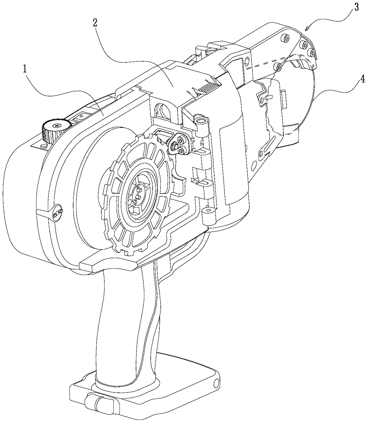
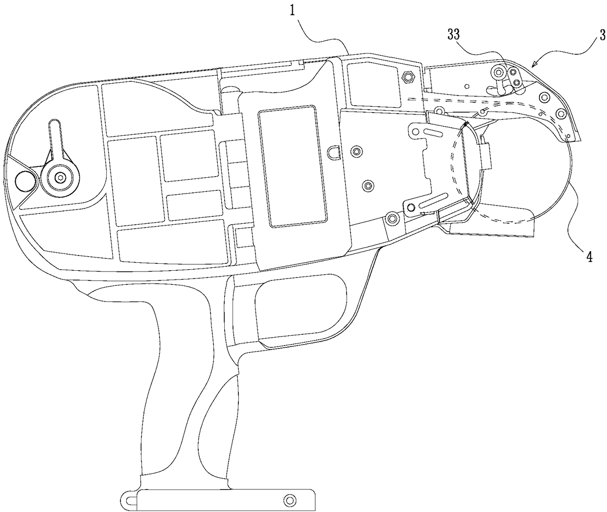
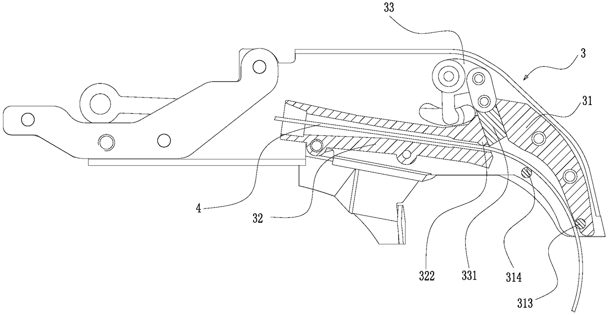
[0033] Such as Figure 1 to Figure 5 As shown, an integrated wire outlet guide mechanism includes a crimped wire outlet part 31 and a wire guide part 32, and the crimped wire outlet part 31 and the wire guide part 32 are laterally formed on a sheet-shaped substrate according to the front and rear positions. A longitudinal groove 34 is provided between the curled wire outlet part 31 and the wire guide part 32, and a boss 311 is provided on the curled wire outlet part 31, and the arc-shaped wall 316 of the boss 311 is lower than the curled wire outlet part 31. A guide portion 312 for guiding the movement of the steel wire is formed on the surface area 317 of the boss 311 , and two guide pieces are arranged in the guide portion 312 . The guide part 312 includes a first steel wire input end A and a first steel wire output end B. A guide member made of a wear-resistant material capable of contacting the steel wire 4 is embedded on the boss 311. The guide member serves as The first...

Embodiment 2

[0040] Figure 6 to Figure 8 As shown, the difference between the structure of the integrated wire outlet guide mechanism and the first embodiment is that a guide is embedded on the upper edge of the second steel wire output end D of the groove 321 as the third guide 323, so The third guiding member 323 is cylindrical. The steel wire 4 passes through the third guide 323 , the second guide 314 and the first guide 313 in sequence, and then bends into a circle.

Embodiment 3

[0042] Such as Figure 9 As shown, the difference between the structure of the integrated wire outlet and guide wire mechanism and that of Embodiment 1 is that the first guide 313 is a straight strip member, and the straight strip member is embedded in the At the first steel wire output end B of the guide part 312, and close to the arc-shaped wall 316 of the boss 311, the steel wire 4 enters the curled wire outlet 31 and moves along the arc-shaped wall 316 of the boss 311. The strip-shaped members contact to complete the crimping of the steel wire 4, and the in-line strip-shaped member can increase the contact area between the steel wire 4 and the guide piece, and the guiding effect is good.


PUM


Abstract

The invention discloses an integrated wire discharge and guide mechanism and a rebar tying machine and belongs to the field of rebar tying devices. According to the technical scheme, in order to solve the problems that in the prior art, the number of component parts of a guide structure of a rebar tying machine is large, machining is complex, dimension error accumulation and installation position deviation are liable to occur, and the steel wire circle formation dimension is not stable or steel wires cannot extend out, the integrated wire discharge and guide mechanism comprises a curved wire discharge part and a wire guide part, wherein the curved wire discharge part and the wire guide part are transversely formed on a sheet substrate in a front-and-back mode, a longitudinal groove is formed between the curved wire discharge part and the wire guide part, the curved wire discharge part is provided with a boss, the arc wall of the boss and the surface area of the curved wire discharge part form a guide part which is used for guiding the steel wires to move, and at least one guide piece is arranged in the guide part. The wire discharge part and the wire guide part are integrally formed, the number of the parts is small, machining and formation are convenient, dimension error accumulation and installation position deviation are reduced, the steel wire circle formation dimension is stable, and the steel wires can extend out smoothly.

Description

technical field [0001] The invention belongs to the field of steel bar binding devices, in particular to an integrated wire outlet and guide wire mechanism and a steel bar binding machine. Background technique [0002] In building construction, in order to improve the strength of reinforced concrete, it is necessary to bundle and reinforce the crossed steel frames before concrete pouring to make them integrated. The steel bar binding machine can replace manual binding, which generally includes a sending mechanism for sending out the steel wire binding wire wound on the reel, a guiding mechanism for guiding the binding wire to wind at the intersection of the steel bars, and twisting the binding wire wound on the steel bar. The strapping wire twisting mechanism is equipped with a special strapping wire twisting mechanism, and the starter is operated to make the strapping wire pass through the sending mechanism, the guiding mechanism and the strapping wire twisting mechanism in...

Claims


Application Information

Patent Timeline
Patent Type & Authority Patents(China)
IPC IPC(8): E04G21/12
CPCE04G21/123
Inventor 陆福军王灵超
Owner TAIZHOU XINDALU ELECTRONICS TECH
Why Eureka
Try Eureka