Dry friction rotary seal device for numerical control punching machine

A CNC punching machine and rotary sealing technology, which is applied in the direction of engine seals, bearing components, engine components, etc., can solve problems such as wear and seal failure, and achieve the effect of ensuring reliability and avoiding corrosion

Active Publication Date: 2017-04-26
朱斌
View PDF13 Cites 9 Cited by
  • Summary
  • Abstract
  • Description
  • Claims
  • Application Information

AI Technical Summary

Problems solved by technology

[0004] The purpose of the present invention is to provide a dry friction rotary sealing device for a CNC punching machine, which solves the technical problem of seal failure caused by wear and tear on the basis of reducing noise through a unique friction pair structure

Method used


Image

  • Dry friction rotary seal device for numerical control punching machine
  • Dry friction rotary seal device for numerical control punching machine
  • Dry friction rotary seal device for numerical control punching machine

Examples


Embodiment 1

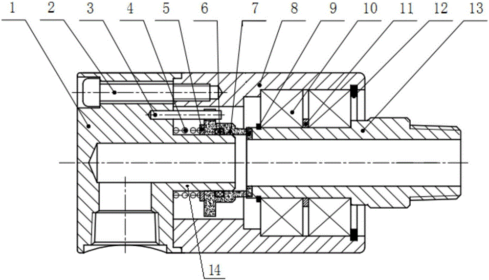
[0030] refer to figure 1 , this embodiment provides a dry friction rotary sealing device for a CNC punching machine, which is suitable for the sealing between the back cover 1 and the corresponding hollow shaft 13 of a CNC punching machine, and the fluid medium flows through the back cover 1 and the hollow shaft in turn. For the rotating shaft 13 , the fluid medium may be used for cooling the hollow rotating shaft 13 , for example. It should be noted that the structure is relatively complicated. In order to simplify the drawings for easy understanding, only the local structure directly related to the sealing device is shown in the drawing. For other structural components of the CNC punching machine, they are all existing structures. For this Invented innovations are not linked and therefore not exhaustively shown in the figure.

[0031] In this embodiment, the rear cover 1 is fixed, and the hollow rotating shaft 13 rotates at a high speed relative to the rear cover 1 . In or...

Embodiment 2

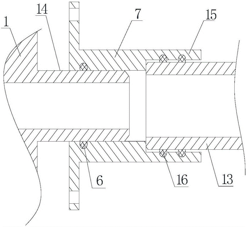
[0044] refer to figure 2 , this embodiment also provides a dry friction rotary sealing device for a CNC punching machine, which is a further improvement on the basis of the technical solution of the first embodiment, and the technical solution described in the first embodiment also belongs to this embodiment, and the first embodiment The described technical solutions will not be repeated.

[0045] It should be noted, figure 2 mainly shows the relative figure 1 features further improved by the structure shown and, therefore, are not shown in full figure 1 other structures.

[0046] On the basis of the technical solution of Embodiment 1, this embodiment mainly adds a main seal extension ring 15, whose main function is that when the alarm in Embodiment 1 fails or other reasons cause the main seal ring 7 to be replaced in time , the end face seal fails unexpectedly, and the main seal extension ring 15 can ensure the sealing effect on the main seal ring 7 and the hollow rotat...


PUM


Abstract

The invention provides a dry friction rotary seal device for a numerical control punching machine. The seal device comprises a rear cover boss, a main seal ring and a compensating spring. The rear cover boss is of a shaft structure. A gap is arranged between the head end of the rear cover boss and the corresponding end face of a hollow rotary shaft. A cavity extending in the axial direction of the rear cover boss is formed in the rear cover boss. The rear cover boss is sleeved with the main seal ring. Seal is formed between the end face of the head end of the main sealing ring and the end face of the hollow rotary shaft. The rear cover boss is sleeved with the compensating spring in a compressed state and used for making the main seal ring always in the trend of moving towards the hollow rotary shaft. The dry friction rotary seal device solves the technical problem of the seal failure caused by wear on the basis of lowering the noise.

Description

technical field [0001] The invention relates to the field of numerically controlled punching machines, in particular to a dry friction rotary sealing device suitable for numerically controlled punching machines. Background technique [0002] The end of the rotating shaft of the CNC punching machine is equipped with a corresponding back cover. The rotating shaft usually adopts a hollow structure, that is, a hollow rotating shaft. The back cover is provided with a fluid channel and an inlet and outlet of the fluid medium. The tunnel is used to realize the functions of cooling the rotating shaft and the like. The sealing technology between the back cover and the hollow shaft has always been a difficult problem in the industry. [0003] The current main sealing method is to directly embed the main seal between the back cover and the hollow shaft to achieve dynamic sealing. This technical means has at least the following defects: First, the main seal is made of relatively soft m...

Claims


Application Information

Patent Timeline
Patent Type & Authority Applications(China)
IPC IPC(8): F16J15/34F16C35/00
CPCF16C35/00F16J15/3452F16J15/3464F16J15/3492
Inventor 朱斌陈惠玲严巧珠郑华婷朱路林月香林晓平陈杰峰廖长洋傅载传
Owner 朱斌
Why Eureka
Try Eureka