Positioning system and positioning method and device thereof and robot
A positioning system and positioning method technology, applied in the field of positioning, can solve the problem of low positioning accuracy of the SLAM system
- Summary
- Abstract
- Description
- Claims
- Application Information
AI Technical Summary
Problems solved by technology
Method used
Image

Examples
Embodiment 1
[0035] An embodiment of the present invention provides a positioning system.
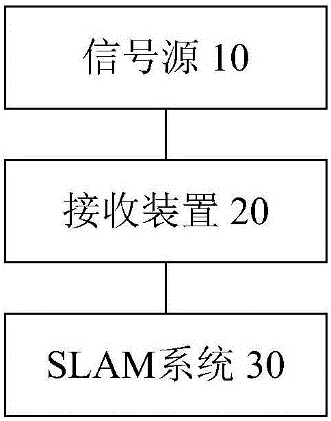
[0036] figure 1 is a schematic structural diagram of a positioning system according to an embodiment of the present invention. Such as figure 1 As shown, the positioning system includes: a signal source 10 , a receiving device 20 and a SLAM system 30 .
[0037] The signal source 10 is configured to send out a visible light signal, wherein the visible light signal is a coded signal and carries information for indicating the location of the signal source.
[0038] Visible light is light in a specific frequency band that can be perceived by human eyes in the electromagnetic spectrum. The signal source 10 is used to emit visible light signals, which can be collected by camera devices, for example, by conventional RGB cameras of smart mobile devices. Optionally, the signal source 10 is a modulated light-emitting diode (Light-Emitting Diode, LED for short), and multiple LED lamps are uniformly deployed...
Embodiment 2
[0066] The embodiment of the invention also provides a robot.
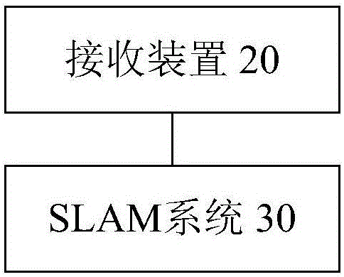
[0067] figure 2 is a structural schematic diagram of a robot according to an embodiment of the present invention. Such as figure 2 As shown, the robot includes: a receiving device 20 and a SLAM system 30 .
[0068] The receiving device 20 is configured to obtain a visible light signal through visible light communication, and decode the visible light signal to obtain first position information of the signal source, wherein the visible light signal is a coded signal sent by the signal source, and carries a signal used to indicate the signal source location information.
[0069] The receiving device 20 may be a LIFI receiving device. The receiving device 20 receives the visible light signal through visible light communication, decodes the visible light signal, and obtains the first position information of the signal source. By analyzing the first position information, information such as distance and orientati...
Embodiment 3
[0078] The embodiment of the present invention also provides a positioning method of the positioning system. It should be noted that the positioning method of the positioning system in this embodiment may be executed by the positioning system in the embodiment of the present invention.
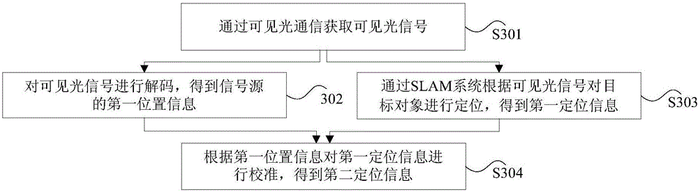
[0079] image 3 It is a flowchart of a positioning method of a positioning system according to an embodiment of the present invention. Such as image 3 As shown, the positioning method of the positioning system includes the following steps:
[0080] Step S301, acquiring a visible light signal through visible light communication.
[0081] In the technical solution provided in step S301 of the present invention, the visible light signal is obtained through visible light communication, wherein the visible light signal is a coded signal sent by the signal source and carries information indicating the location of the signal source.
[0082] Visible light communication is a communication method ...
PUM
 Abstract
Description
Claims
Application Information
 - R&D
- Intellectual Property
- Life Sciences
- Materials
- Tech Scout
- Unparalleled Data Quality
- Higher Quality Content
- 60% Fewer Hallucinations
Browse by: Latest US Patents, China's latest patents, Technical Efficacy Thesaurus, Application Domain, Technology Topic, Popular Technical Reports.
© 2025 PatSnap. All rights reserved.Legal|Privacy policy|Modern Slavery Act Transparency Statement|Sitemap|About US| Contact US: help@patsnap.com