Supercharge Your Innovation With Domain-Expert AI Agents!

Position and orientation measuring and calculating optical instrument and debugging method thereof

A technology of optical instruments and debugging methods, which is applied in the directions of instruments, measuring devices, surveying and navigation, etc., can solve the problems of low reliability of measurement data and complicated debugging process, and achieve high reliability of measurement data and small envelope size , the effect of low processing difficulty

Active Publication Date: 2017-04-26
XI'AN INST OF OPTICS & FINE MECHANICS - CHINESE ACAD OF SCI
View PDF4 Cites 13 Cited by
  • Summary
  • Abstract
  • Description
  • Claims
  • Application Information

AI Technical Summary

Problems solved by technology

The position and attitude measurement instrument must ensure the measurement accuracy under the complex space environment load, and must also withstand the harsh mechanical loads such as large-scale vibration and impact during rocket launch and satellite rocket separation. The existing position and attitude measurement optical instruments can measure data. Low reliability, unable to withstand harsh mechanical and thermal environments
At the same time, due to the constraints of launch cost, use efficiency and other factors, the pose measurement instrument must meet a series of conditions such as light weight and high reliability. In addition, the existing pose measurement optical instrument has a complicated debugging process

Method used


Image

  • Position and orientation measuring and calculating optical instrument and debugging method thereof
  • Position and orientation measuring and calculating optical instrument and debugging method thereof
  • Position and orientation measuring and calculating optical instrument and debugging method thereof

Examples


Embodiment Construction

[0026] Below in conjunction with accompanying drawing and specific embodiment content of the present invention is described in further detail:

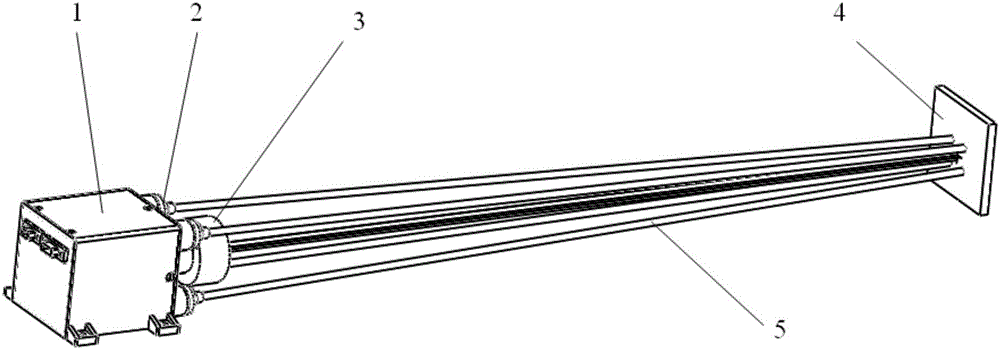
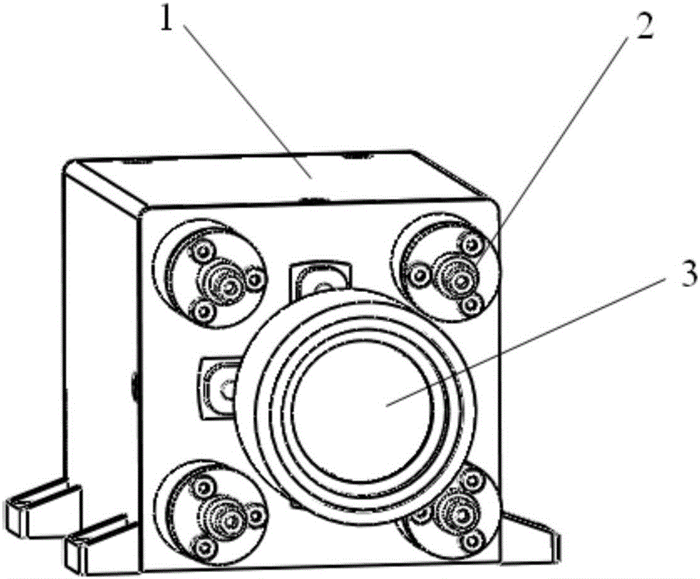
[0027] Such as figure 1 , figure 2 , image 3 The shown pose measurement optical instrument includes an optical camera 1, four laser components 2 and an optical lens 3; the laser component 2 and the optical lens 3 are all arranged on the optical camera 1, and the installation surface is the same plane; the optical lens 3 is A large field of view optical lens that meets the technical requirements for pose measurement and calculation is fixedly connected to the optical camera 1 through screws. The optical camera 1 is provided with an image detector and an image data processing circuit; the optical axis of the optical lens 3 coincides with the visual axis of the image detector, the optical axis of the optical lens 3 is perpendicular to the photosensitive surface of the image detector, and the center of the optical lens 3 is aligned wi...


PUM


Abstract

The invention relates to the field of optical measuring devices, in particular, relates to a position and orientation measuring and calculating optical instrument and a debugging method thereof, and is used for mainly solving the problems that a conventional position and orientation measuring and calculating instrument has low reliability of measurement data and cannot withstand harsh mechanical and thermal environments and the debugging process of the position and orientation measuring and calculating instrument is complicated. The position and orientation measuring and calculating instrument includes an optical camera, a plurality of laser assemblies and an optical lens; the laser assemblies and the optical lens are all arranged on the optical camera; the optical camera is provided with an image detector and an image data processing circuit; the optical axis of the optical lens is coincident to the visual axis of the image detector, and the optical axis of the optical lens is perpendicular to the light-sensitive surface of the image detector; the laser assemblies each comprise a laser and an adjusting pad, the adjusting pads are arranged between the lasers and the optical camera, the plurality of laser assemblies are uniformly distributed in the circumferential direction with the optical axis of the optical lens as the center, and a certain included angle is formed between the optical axis of each laser and the optical axis of the optical lens.

Description

technical field [0001] The invention relates to the field of optical measuring devices, in particular to an optical instrument for measuring and calculating a pose and a debugging method. Background technique [0002] With the further development of space optics technology, space loads are also constantly innovating. In recent years, various types of new loads have emerged, including large robotic arms and other equipment that achieve task requirements through mechanical movement. When this kind of equipment is in use, due to unfavorable factors such as the space environment, the inaccessibility of human hands and eyes, or close observation of the equipment, such equipment must use some measurement method to accurately calculate the real-time position and attitude of the equipment, that is, it needs Perform real-time pose estimation on the device. [0003] The space environment has the characteristics of weightlessness and significant temperature changes, which put forward ...

Claims


Application Information

Patent Timeline
Patent Type & Authority Applications(China)
IPC IPC(8): G01C21/00G01C25/00
CPCG01C21/00G01C25/00
Inventor 柴文义许哲宋宗玺袁灏朱波黄超
Owner XI'AN INST OF OPTICS & FINE MECHANICS - CHINESE ACAD OF SCI
Features
  • R&D
  • Intellectual Property
  • Life Sciences
  • Materials
  • Tech Scout
  • Unparalleled Data Quality
  • Higher Quality Content
  • 60% Fewer Hallucinations
Learn More