Miniaturized photoelectric passive distance measuring device

A passive ranging and photoelectric technology, applied in the direction of measuring devices, radio wave measuring systems, instruments, etc., can solve the problems of low accuracy of distance inversion, bulky system, difficulty in coplanarity, etc., and achieve miniaturized design and high ranging The effect of precision

Active Publication Date: 2019-01-18
山东中科际联光电集成技术研究院有限公司
View PDF3 Cites 0 Cited by
  • Summary
  • Abstract
  • Description
  • Claims
  • Application Information

AI Technical Summary

Problems solved by technology

[0005] In order to solve the problems caused by the bulky system in traditional multi-station ranging, the difficulty of coplanar imaging horizontal datum planes between multi-stations, large measurement errors between datum planes under non-coplanar conditions, and consistency errors in the measurement of target inclination angles between multi-stations, etc. To solve the problem of low accuracy of distance inversion, a miniaturized photoelectric passive ranging device is proposed. The optical path difference is formed through the reentrant optical path conversion, which can greatly reduce the volume and weight of the device, and realize coaxial imaging between multiple sensors. Improve the distance measurement accuracy, which is beneficial to the engineering application of related technologies

Method used


Image

  • Miniaturized photoelectric passive distance measuring device
  • Miniaturized photoelectric passive distance measuring device
  • Miniaturized photoelectric passive distance measuring device

Examples


Embodiment Construction

[0021] Descriptions of structural embodiments of the present invention are disclosed herein. It will be appreciated that the intention is not to limit the invention to the particular disclosed embodiments, but that the invention can be practiced using other features, elements, methods and embodiments. Similar elements in different embodiments are generally labeled with similar numbers.

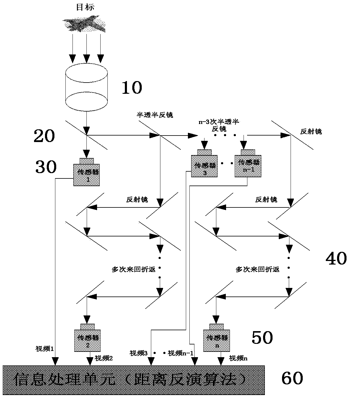
[0022] see figure 1 and figure 2 As shown, the present invention provides a miniaturized photoelectric passive distance measuring device ( figure 1 ), including:

[0023] An optical receiving telescope 10;

[0024] A row of half-mirrors 20, the first half-mirror is located on the optical path of the optical receiving telescope 10, and receives the signal of the optical receiving telescope 10, and transmits and reflects it, the second half-mirror The mirror receives the reflection signal of the first half mirror, and the remaining half mirrors receive the transmission signal of the previo...


PUM


Abstract

The invention discloses a miniature photoelectric passive distance measuring device, which comprises an optical receiving telescope, a row of half transparent and half reflecting mirrors, a first row of imaging sensors, a reflector group, a second row of imaging sensors, and an information processing unit, wherein the first half transparent and half reflecting mirror is located on the optical path of the optical receiving telescope, receives signals of the telescope and transmits and reflects the signals; the second half transparent and half reflecting mirror receives reflection signals of the first half transparent and half reflecting mirror; and each of the rest half transparent and half reflecting mirror receives transmission signals of the former half transparent and half reflecting mirror sequentially, the received signals are transmitted and then reflected, and multiple optical paths are formed; the first imaging sensor receives transmission signals of the first half transparent and half reflecting mirror; each of the rest imaging sensors is located on the reflection optical path of the (odd number)th half transparent and half reflecting mirror; the reflector group receives reflection signals of the (even number)th half transparent and half reflecting mirror; the second row of imaging sensors receives reflection signals of each reflector group; and the information processing unit receives video signals of multiple optical paths of the first row of imaging sensors and the second row of imaging sensors, and distance inversion algorithm processing is carried out on the received video signals.

Description

technical field [0001] The invention belongs to the technical field of photoelectric positioning and photoelectric countermeasures, and in particular relates to a miniaturized photoelectric passive distance measuring device. Background technique [0002] With the continuous advancement of new military technology changes, high-tech weapons such as precision guidance and fixed-point strikes emerge in an endless stream, becoming the main battlefield for various military powers. The premise of precision strike lies in high-precision target situational awareness, not only the two-dimensional intensity information of the target, but also the distance and orientation information of the target. Among them, the distance information is the basis of positioning, so in the photoelectric positioning and orientation, the most core is the photoelectric ranging technology. [0003] Photoelectric ranging technology is mainly divided into active ranging technology and passive ranging technol...

Claims


Application Information

Patent Timeline
Patent Type & Authority Patents(China)
IPC IPC(8): G01S11/12
CPCG01S11/12
Inventor 杨金宝刘建国祝宁华
Owner 山东中科际联光电集成技术研究院有限公司
Why Eureka
Try Eureka