
A control device based on light signal and psd

A control device and optical signal technology, applied in the field of security control, can solve problems such as complex circuit connections, and achieve the effect of large password capacity, not easy to be cracked, and not easy to repeat

Active Publication Date: 2020-02-28
CHANGSHA UNIVERSITY OF SCIENCE AND TECHNOLOGY
View PDF1 Cites 0 Cited by
  • Summary
  • Abstract
  • Description
  • Claims
  • Application Information

AI Technical Summary

Problems solved by technology

The Chinese patent document with the application number 201410501058.4 discloses a security control device based on optical cryptography. The security control device uses optical cryptography and has high confidentiality, but the circuit connection is relatively complicated when the password is compiled.

Method used


Image

  • A control device based on light signal and psd
  • A control device based on light signal and psd
  • A control device based on light signal and psd

Examples


Embodiment 1

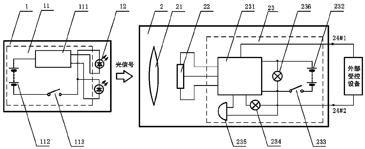
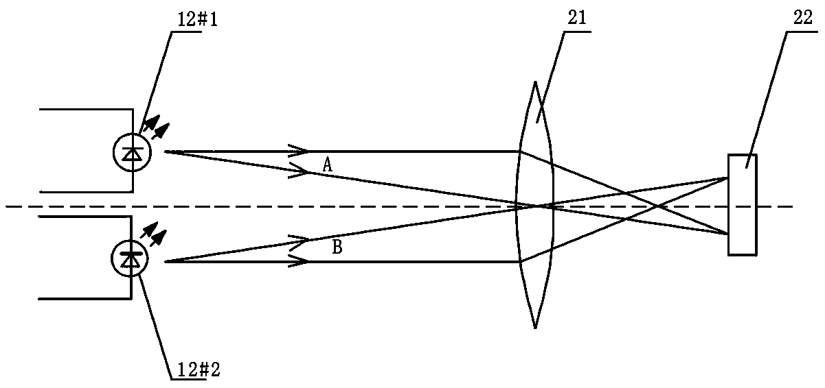
[0023] like figure 1 As shown, the control device based on optical signal and PSD in this embodiment includes an optical signal generator 1 and a receiving controller 2, and the optical signal generator 1 includes an optical signal generation control unit 11 and two LED light sources 12, and the LED light source 12 and the optical signal The output terminal of the generation control unit 11 is connected, and the receiving controller 2 includes an imaging lens 21, a PSD position sensor 22 and a receiving control circuit 23. The light signal sent by the LED light source 12 is imaged on the PSD position sensor 22 after passing through the imaging lens 21, and the PSD position The output terminal of the sensor 22 is connected with the receiving control circuit 23, and the receiving control circuit 23 is provided with a control output terminal for connecting with an external controlled device (see figure 1 24#1 and 24#2 in the two connection ends).

[0024] like figure 1 As shown...

Embodiment 2

[0033] This embodiment is basically the same as Embodiment 1, the main difference being that the number of LED light sources 12 is different, see Figure 4 , the number of LED light sources 12 in this embodiment is one.

Embodiment 3

[0035] This embodiment is basically the same as Embodiment 1, the main difference being that the number of LED light sources 12 is different, see Figure 5 , the number of LED light sources 12 in this embodiment is three.


PUM


Abstract

The invention discloses a control device based on a light signal and a PSD (Position Sensitive Device). The control device comprises a light signal generator and a receiving controller, wherein the light signal generator comprises a light signal generation control unit and at least one LED (Light-Emitting Diode) light source; the LED light source is connected with the output end of the light signal generation control unit; the receiving controller comprises an imaging lens, the PSD and a receiving control circuit; the light signal emitted by the LED light source is imaged on the PSD after passing through the imaging lens; the output end of the PSD is connected with the receiving control circuit; the receiving control circuit is provided with a control output terminal which is connected with external controlled equipment. The control device has the advantages of simple structure, convenience in use, high interference resistance, extremely high security, saving in energy and environmental friendliness.

Description

technical field [0001] The invention relates to the technical field of safety control, in particular to a control device based on optical signals and PSD, which is used for safety control of external controlled equipment. Background technique [0002] In order to safely control such as housing doors, office doors, cars, safes, machines or large equipment, etc., people generally use key locks or combination locks to control them. Only with the correct key or password can they be opened normally. Key lock is the most common way, which is simple and convenient, but the security is not high. There are various types of combination locks, such as mechanical combination locks, electronic combination locks, magnetic card combination locks and wireless electronic combination locks, etc. These encryption methods have their own advantages and disadvantages. For the electronic combination lock that is now commonly used, the electromagnetic radiation produced by more and more powerful ...

Claims


Application Information

Patent Timeline
Patent Type & Authority Patents(China)
IPC IPC(8): G07C9/00
CPCG07C9/00174G07C9/00817G07C2009/00785
Inventor 彭润伍
Owner CHANGSHA UNIVERSITY OF SCIENCE AND TECHNOLOGY
Learn More