

Airless tire
A technology of airless tires and tires, applied to non-pneumatic tires, tire parts, wheels, etc., can solve problems such as damage, and achieve the effect of improving durability and excellent ride comfort
Active Publication Date: 2017-05-03
SUMITOMO RUBBER IND LTD
View PDF18 Cites 8 Cited by
- Summary
- Abstract
- Description
- Claims
- Application Information
AI Technical Summary
Problems solved by technology
[0014] As described above, in order to improve ride comfort, in an airless tire having spokes arranged obliquely with respect to the radial surface of the tire, deformation tends to concentrate on the outer end side in the tire radial direction of the spokes. Part of the starting point is the problem of early damage
Method used
View moreImage
Smart ImageViewing Examples

Examples
Embodiment
[0067] trial production Figure 1~4 Airless tires of the basic construction (equivalent to tires with a tire size of 125 / 80R13) were tested for durability, tire weight, and TFV. The structures other than the spokes are substantially the same for each tire. The spokes are molded integrally with the tread ring and the hub portion via an adhesive layer by a polyurethane resin (thermosetting resin) casting method. The main shared specifications are as follows.
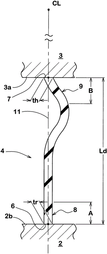
[0068] The shortest distance Ld of the spokes: 80mm
[0069] The thickness t of the inner end side of the spoke h : 3mm
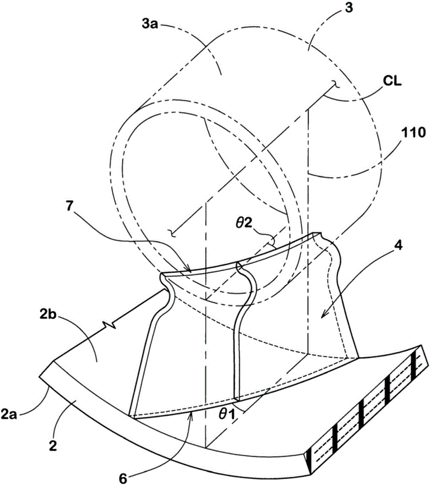
[0070] Spoke angle θ1, θ2: 20 degrees
Login to View More PUM
 Abstract
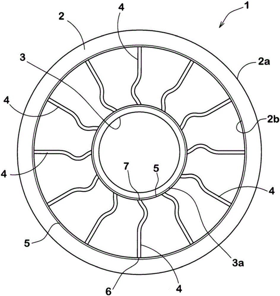
The invention relates to an airless tire that is excellent in durability. The airless tire 1 includes a cylindrical tread ring 2 that is formed of an elastic body and has a ground contact surface (2a), a hub part 3 that is formed of a substantially non-extensible material and that is arranged on a tire radial direction inner side of the tread ring 2 and is fixed to an axle, and multiple spokes 4 that are formed of an elastic material and are for connecting the tread ring 2 and the hub part 3. The spokes 4 each have the outer edge 6 that is fixed to the tread ring 2 side and the inner edge 7 that is fixed to the hub part 3 side. The outer edge 6 and the inner edge 7 both extend obliquely with respect to a tire axial direction. A compression rigidity (Sr) of the outer edge 6 side of each of the spokes 4 is larger than a compression rigidity (Sh) of the inner edge 7 side of each of the spokes 4.
Description
technical field [0001] The present invention relates to an airless tire capable of supporting a load by its own structure without using high-pressure air. Background technique [0002] In recent years, various airless tires have been proposed by the following patent documents 1 to 4 and the like. An airless tire can support a load by its own structure without using high-pressure air. Therefore airless tire has the advantage of not blowing out. [0003] exist Figure 6 A side view of a typical airless tire 100 is shown in . The airless tire 100 has: a cylindrical tread ring 102 having a contact surface made of an elastic body; a metal hub portion 106 arranged radially inside the tread ring 102 and fixed to the axle 104; spokes 108, which are used to connect the tread ring 102 to the hub portion 106. Each spoke 108 is made of, for example, a relatively soft elastomer material, and has an outer end 108 a fixed to the tread ring 102 side, and an inner end 108 b fixed to the ...
Claims
Login to View More Application Information
Patent Timeline
 IPC IPC(8): B60B9/26
CPCB60B9/26B60B2900/313B60C7/143B60C7/18B60C7/146B60C7/14
Inventor岩村和光杉谷信
OwnerSUMITOMO RUBBER IND LTD