
Overlaid assembly-type concrete dense-rib floor structure system and construction method for same

A dense-ribbed floor and concrete technology, which is applied to floors, building components, building structures, etc., can solve the problems of high quality of hollow floors, time-consuming and labor-intensive removal of formwork, and easy occurrence of air bubbles in the lower flange, so as to achieve construction The workload is reduced, the template and supporting tools are saved, and the self-weight is reduced.

Inactive Publication Date: 2017-05-03
CHANGSHA BROAD HOMES IND GRP CO LED
View PDF6 Cites 7 Cited by
  • Summary
  • Abstract
  • Description
  • Claims
  • Application Information

AI Technical Summary

Problems solved by technology

However, the fully cast-in-place concrete hollow floor requires a large number of supporting and folding formwork and supporting tool-type support systems. The amount of work is large and the operation is complicated. Generally, specialized wooden formwork workers are required. There are many formwork, high cost, long construction period, and water After concrete, it is time-consuming and labor-intensive to remove the formwork
At the same time, the thickness of the lower flange of the fully cast-in-place concrete hollow floor is relatively thin. When pouring concrete, the lower flange is prone to air bubbles, cavities, etc., which will affect the quality of the floor.
In addition, when the concrete is poured, the empty box will be subject to a large buoyancy force and float upwards. Therefore, it is necessary to add spacers between the steel bars and the empty box to ensure the thickness of the upper flange. Therefore, it is difficult to ensure the quality of the hollow floor Big

Method used


Image

  • Overlaid assembly-type concrete dense-rib floor structure system and construction method for same
  • Overlaid assembly-type concrete dense-rib floor structure system and construction method for same
  • Overlaid assembly-type concrete dense-rib floor structure system and construction method for same

Examples


Embodiment

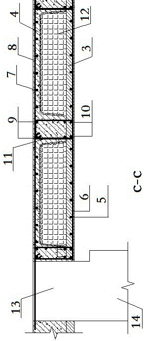
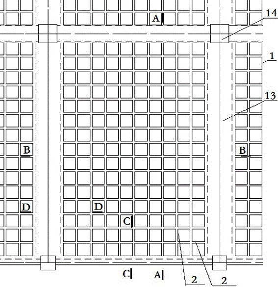
[0054] Example: In the superimposed prefabricated concrete ribbed floor, the cast-in-place thickness of the top of the slab is 50-100mm, the prefabricated thickness of the bottom of the slab is 60-100mm, the size of the foam box in the middle is 500x500-900x900mm, and the width of the longitudinal rib is 150-200mm. The width of the transverse rib beam is 150~200mm. During the construction process, the bottom formwork of the floor slab is formed by prefabricating the bottom slab and the intermediate foam box. After the upper steel bars are installed, concrete is poured to form a densely ribbed floor slab. Most of the concrete outside the tension is removed, and the rest is marked with "工" and "T". The shaped beam bears the vertical load, and the force is more reasonable, which greatly reduces the self-weight of the floor slab, and saves materials such as formwork, steel bars and concrete.


PUM


Abstract

The invention provides an overlaid assembly-type concrete dense-rib floor structure system and a construction method for the same. The system comprises a baseplate and a top plate, wherein the baseplate is composed of multiple prefabricated baseplates which have the same division width and are connected by overlaying steel bars; the top plate is a cast-in-situ top plate with a rib beam; the base plate and the top plate are overlaid and assembled; and a force bearing steel bar which is in overlapped connection with an overlaid beam steel bar is stretched out from an end head of the rib beam. The construction method comprises the steps that the prefabricated baseplate is prepared at a plant; hoisting is conducted on site; rib beam stirrups and rib beam reinforcing bars are disposed, and a hollow box or light material body is disposed; structural steel bars of the top plate are disposed; the rib beam reinforcing bars stretch out from the lateral sides and are in overlapped connection with the overlaid beam; and concrete pouring, maintenance and shaping are carried out. According to the invention, erection and dismounting of templates and supporting tools are omitted; work loads are reduced; construction cost is reduced; construction efficiency is increased; force bearing is more rational; and quality is better.

Description

technical field [0001] The invention belongs to the technical field of construction engineering, and in particular relates to a superimposed and assembled concrete ribbed floor structure system and a construction method thereof. Background technique [0002] The fully cast-in-place concrete hollow floor has the advantages of saving building materials, reducing self-weight, good integrity, and high structural strength. However, the fully cast-in-place concrete hollow floor requires a large number of supporting and folding formwork and supporting tool-type support systems. The amount of work is large and the operation is complicated. Generally, specialized wooden formwork workers are required. There are many formwork, high cost, long construction period, and water After concrete, removing the formwork is time-consuming and labor-intensive. At the same time, the thickness of the lower flange of the fully cast-in-place concrete hollow floor is relatively thin. When pouring conc...

Claims


Application Information

Patent Timeline
IPC IPC(8): E04B5/21E04G21/14
CPCE04B5/21E04G21/14
Inventor 张剑何磊熊育明彭金林
Owner CHANGSHA BROAD HOMES IND GRP CO LED
Learn More