Periodic oriented flow guide device for various types of fluid

A diversion device, periodic technology, applied in the direction of valve device, multi-way valve, slide valve, etc., can solve the load limit and other problems, and achieve the effect of easy sealing, small sealing area and light weight

Active Publication Date: 2017-05-03
SUZHOU MICROWANTS BIOLOGICAL TECH CO LTD
View PDF12 Cites 2 Cited by
  • Summary
  • Abstract
  • Description
  • Claims
  • Application Information

AI Technical Summary

Problems solved by technology

The structure disclosed in US5676826 faces challenges such as the synchronization of the rotation of the reactor and the valve, and the load limitation of the rotating carrier of the reactor.

Method used


Image

  • Periodic oriented flow guide device for various types of fluid
  • Periodic oriented flow guide device for various types of fluid
  • Periodic oriented flow guide device for various types of fluid

Examples


Embodiment Construction

[0034] The present invention will be described in detail below in conjunction with the accompanying drawings and embodiments.

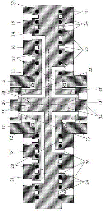
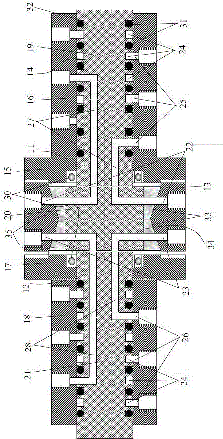
[0035] like figure 1As shown, the present invention includes stators 11, 12, 13 and rotor 14, wherein the first stator 11 includes a flange 15 and a thick-walled tube 16, and the second stator 12 includes a flange 17 and a thick-walled tube 18; the rotor 13 is a cylinder 19-double cone 20-cylinder 21 structure, the rotor 14 is positioned on the first stator 11 and the second stator 12 through the bearing 30, and is rotatably arranged on the first stator 11 and the second stator 12 and the space enclosed by the third stator 13.

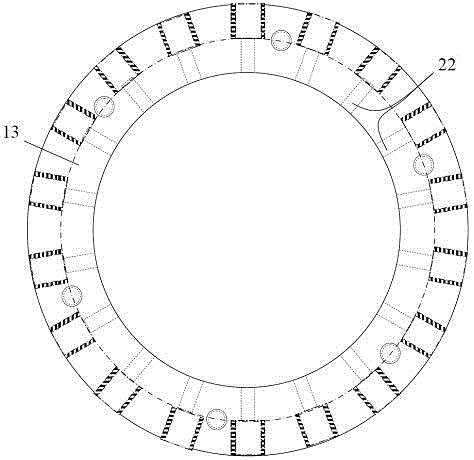
[0036] A plurality of stator distribution channels 22 and a plurality of stator collection channels 23 are arranged inside the third stator 13; each stator distribution channel 22 is radially and evenly distributed in the same section of the third stator 13 (such as figure 2 shown), each stator distribution channel 22 forms...


PUM


Abstract

The invention relates to a periodic oriented flow guide device for various types of fluid. The periodic oriented flow guide device comprises three stators and a rotor, wherein two of the three stators are of thick-wall pipe structures with relatively small diameters, and one end of each of the two stators is provided with a flange; the other stator is of a thick-wall pipe structure with a relatively large diameter; the rotor is of a cylinder-double cone-cylinder structure or a cylinder-cylinder-cylinder structure, and is arranged in a space surrounded by the three stators in a ratable manner; a plurality of stator distribution channels and a plurality of stator collection channels are formed in the third stator; a plurality of circumferential channels are formed in the cylindrical surface of the rotor in a spacing manner; a plurality of stator fluid supply channels and a plurality of stator fluid discharging channels are formed in cylindrical pipes of the first and second stators; and a plurality of rotor distribution channels, a plurality of rotor collection channels and a plurality of rotor communicating channels are formed in the rotor.

Description

technical field [0001] The invention relates to a periodic directional guide device for multiple fluids, which is used for directional guide of multiple liquids to independent targets through separate flow paths. Background technique [0002] The multi-channel valve with the periodic directional flow function of various liquids is widely used in the process of physical, chemical and chromatographic analysis. [0003] In 1953, U.S. Patent US2706532 disclosed the structure of the first multi-channel valve. Its structural features are: (1) It includes two disc-shaped stators and a cylindrical rotor. In the same stator; (2) The opening connecting the rotor passage and the stator passage and the liquid supply and discharge circumferential passage are located on both ends of the rotor, and the rotor and the stator are sealed by two planes. [0004] In 1959, the UOP company of the United States disclosed the structure of the first marketed multi-channel valve (US3040777). Its stru...

Claims


Application Information

Patent Timeline
Patent Type & Authority Applications(China)
IPC IPC(8): F16K11/074F16K3/314
CPCF16K3/314F16K11/0746
Inventor 何克江王季凤刘冰洁
Owner SUZHOU MICROWANTS BIOLOGICAL TECH CO LTD
Why Eureka
Try Eureka