An electronic shower faucet

A shower faucet and electronic technology, applied in the direction of valve details, engine components, mechanical equipment, etc., can solve the problems of easily scalded users, inconvenient adjustment, and lower internal water temperature, and achieve a simple overall structure, avoid cumbersome operations, and rich functions Effect

Active Publication Date: 2017-05-03
FUJIAN XIHE SANITARY WARE TECH
View PDF6 Cites 7 Cited by
  • Summary
  • Abstract
  • Description
  • Claims
  • Application Information

AI Technical Summary

Problems solved by technology

[0002] When using a traditional shower faucet, the user generally obtains the water temperature he needs by adjusting the thermostatic valve core and feeling the water temperature with the skin. This method is not only inconvenient to adjust, but also easy to burn the user
For this reason, the shower faucet with temperature display function has appeared in the prior art, although this shower faucet can let the user know the water temperature of the current shower faucet very intuitively, but when the shower faucet is not used for a period of time, its internal water temperature will As a result, the temperature displayed on the shower faucet is often lower than the temperature required by the user, which easily makes the user mistakenly think that the water temperature is too low and needs to readjust the thermostatic valve core and sense the water temperature through the skin to obtain the water temperature they need. There are also problems such as inconvenient adjustment and easy scalding of users

Method used


Image

  • An electronic shower faucet
  • An electronic shower faucet
  • An electronic shower faucet

Examples


Embodiment Construction

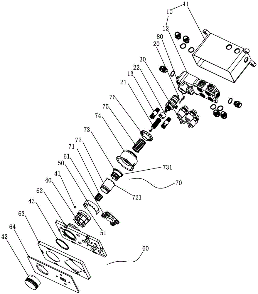
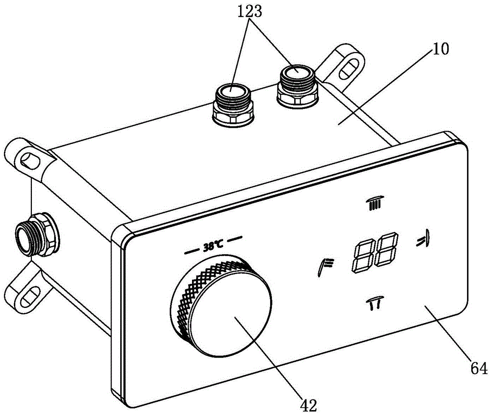
[0041] Examples, see Figure 1-Figure 11 As shown, an electronic shower faucet of the present invention includes a fixed unit 10, a thermostatic valve core 20, and a water outlet control module 30. The thermostatic valve core 20 and the water outlet control module 30 are installed on the fixed unit 10. Knob 40; also includes:

[0042] Several magnetic control elements 51 are arranged on the periphery of the temperature adjustment knob 40 and are located in different radial directions of the temperature adjustment knob 40;

[0043] The magnetic element 41 is arranged on the side of the knob 40, the magnetic element 41 is specifically a magnet, and the magnetic control element 51 is preferably a Hall element;

[0044]The temperature display module 60 includes a display board and a control circuit board, the control circuit board is electrically connected to the display board and each magnetic control element 51, and when the display board is activated, the display board display...


PUM


Abstract

The invention provides an electronic shower faucet comprising a fixing unit, a constant temperature valve element, and a water outlet control module, wherein the constant temperature valve element is connected with a temperature adjusting rotary knob. The electronic shower faucet also comprises a plurality of magnetic control elements which are arranged on the outer periphery of the temperature adjusting rotary knob and located in different radial directions of the temperature adjusting rotary knob; a magnetic element arranged on the knob; a temperature display module comprising a display panel and a control circuit board electrically connected with the display panel and the magnetic control elements. When the display panel is activated, the display panel displays the set temperature of the constant temperature valve element corresponding to the current angular position of the magnetic element; when the display panel is in the activated state, the temperature adjusting rotary knob can change the angular position of the magnetic element through rotation to make the magnetic element inductively cooperate with different magnetic control elements, and the control circuit board controls the display panel to display the set temperature corresponding to the angular position of the magnetic element. The electronic shower faucet requires no complicated operations of repeated temperature adjustment and prevents users from getting scalded when trying water temperature.

Description

technical field [0001] The invention relates to a bathroom product, in particular to an electronic shower faucet. Background technique [0002] When using a traditional shower faucet, the user generally obtains the desired water temperature by adjusting the thermostatic valve core and feeling the water temperature with the skin. This method is not only inconvenient to adjust, but also easily burns the user. For this reason, the shower faucet with temperature display function has appeared in the prior art, although this shower faucet can let the user know the water temperature of the current shower faucet very intuitively, but when the shower faucet is not used for a period of time, its internal water temperature will As a result, the temperature displayed on the shower faucet is often lower than the temperature required by the user, which easily makes the user mistakenly think that the water temperature is too low and needs to readjust the thermostatic valve core and sense t...

Claims


Application Information

Patent Timeline
Patent Type & Authority Applications(China)
IPC IPC(8): F16K37/00F16K31/66
CPCF16K31/002F16K37/0025
Inventor 林孝发林孝山李帅宇刘启乔邓小清
Owner FUJIAN XIHE SANITARY WARE TECH
Why Eureka
Try Eureka