Fool-proof testing device

A technology of testing devices and shielding devices, applied in the direction of instruments, static indicators, etc., can solve problems such as short circuit, overvoltage, hot plug damage, etc., and achieve the effect of avoiding damage

Inactive Publication Date: 2017-05-03
HUAWEI DEVICE CO LTD
View PDF7 Cites 3 Cited by
  • Summary
  • Abstract
  • Description
  • Claims
  • Application Information

AI Technical Summary

Problems solved by technology

[0003] The occurrence of EOS events is mainly during the hot-swapping process of the LCD, and the LCD itself does not have the ability of hot-swapping. Hot-swapping during the working process of the LCD will cause EOS events to occur.
[0004] like figure 1 As shown, the LED+ pin power-off voltage when the LCD is working normally and the LED+ pin power-off voltage change ratio waveform diagram during hot-swapping, from figure 1 It can be seen from the figure that in the process of hot plugging, the voltage of the LED+ pin is instantly increased to about 2 times the original voltage, and the high voltage is maintained for a period of time. If other pins in the LCD are in contact with the LED+ pin at this time, short circuit, overvoltage, etc.
[0005] In the prior art, there is no fool-proof test device that can prevent hot plugging ("fool-proof" is a technical term, and this word comes from Japan (Japanese: ポカヨケ), which is a preventive correction. Constraint means, use the restriction method to avoid errors, so that the operator can intuitively and correctly complete the correct operation without paying attention, experience and professional knowledge), therefore, the problem of LCD damage caused by hot swapping has always been need to be resolved

Method used


Image

  • Fool-proof testing device
  • Fool-proof testing device
  • Fool-proof testing device

Examples


Embodiment Construction

[0026] The technical solutions of the present invention will be described in further detail below with reference to the accompanying drawings and embodiments.

[0027] In order to make the purpose, technical solutions and advantages of the embodiments of the present invention clearer, the technical solutions in the embodiments of the present invention will be clearly and completely described below in conjunction with the drawings in the embodiments of the present invention. Obviously, the described embodiments It is a part of embodiments of the present invention, but not all embodiments. Based on the embodiments of the present invention, all other embodiments obtained by persons of ordinary skill in the art without making creative efforts belong to the protection scope of the present invention.

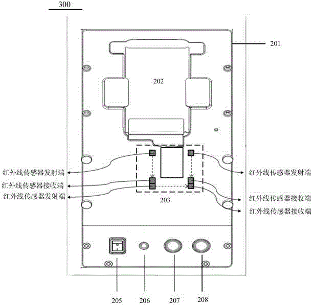
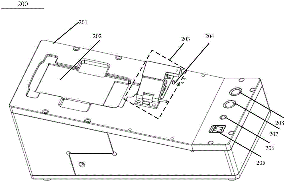
[0028] figure 2 A schematic structural diagram 200 of a fool-proof testing device provided by an embodiment of the present invention. Such as figure 2 As shown, the device includ...


PUM


Abstract

The embodiment of the invention discloses a fool-proof testing device. The device comprises a housing; a groove which is located on the housing; a shielding apparatus which is disposed on the housing and is used for forming a shielding region; and a connector interface which is located in the shielding region. A to-be-detected device is placed in the groove, and is connected with the connector interface through a connector. The housing is additionally provided with the shielding apparatus, thereby forming the shielding region, effectively preventing hot plug operation during electric detection of a device on the testing device, and avoiding the damages to an LCD.

Description

technical field [0001] The invention relates to the application field of liquid crystal displays, in particular to a fool-proof testing device. Background technique [0002] In the liquid crystal display (Liquid Crystal Display, LCD for short) market, some failures inevitably occur in the LCD, such as a black screen problem. In the process of studying the black screen problem, it can be found that the line burn problem is an important cause of the black screen, and this reason can account for 10% of the overall failure of the LCD. When further observing the actual state of the line burn, it can be determined that the cause of the fault is an electrical over stress (Electrical Over Stress, EOS for short) event. EOS is the current applied to the LCD exceeds the specified maximum current. Any EOS event may cause LCD damage. This damage can manifest as LCD failure immediately, or it may fail long after the EOS event occurs. Generally speaking, the conditions that lead to the ...

Claims


Application Information

Patent Timeline
Patent Type & Authority Applications(China)
IPC IPC(8): G09G3/00
CPCG09G3/006
Inventor 王宇飞
Owner HUAWEI DEVICE CO LTD
Why Eureka
Try Eureka