Middle roll-over table of automatic stamping mechanical hand

A technology of turning table and manipulator, applied in metal processing equipment, feeding devices, manufacturing tools, etc., can solve the problem of turning angle and other problems, and achieve the effect of improving utilization rate and simple structure

Active Publication Date: 2017-05-10
SIYANG MINGYUXING PRECISION MACHINERY CO LTD
View PDF8 Cites 11 Cited by
  • Summary
  • Abstract
  • Description
  • Claims
  • Application Information

AI Technical Summary

Problems solved by technology

[0006] The purpose of the present invention is to provide an intermediate turning table for stamping automation manipulators, which solves the problem of the turning angle of the workpiece during the stamping process, enables the workpiece to be quickly transported from one process to another, and automates the entire stamping production line.

Method used


Image

  • Middle roll-over table of automatic stamping mechanical hand
  • Middle roll-over table of automatic stamping mechanical hand
  • Middle roll-over table of automatic stamping mechanical hand

Examples


Embodiment 1

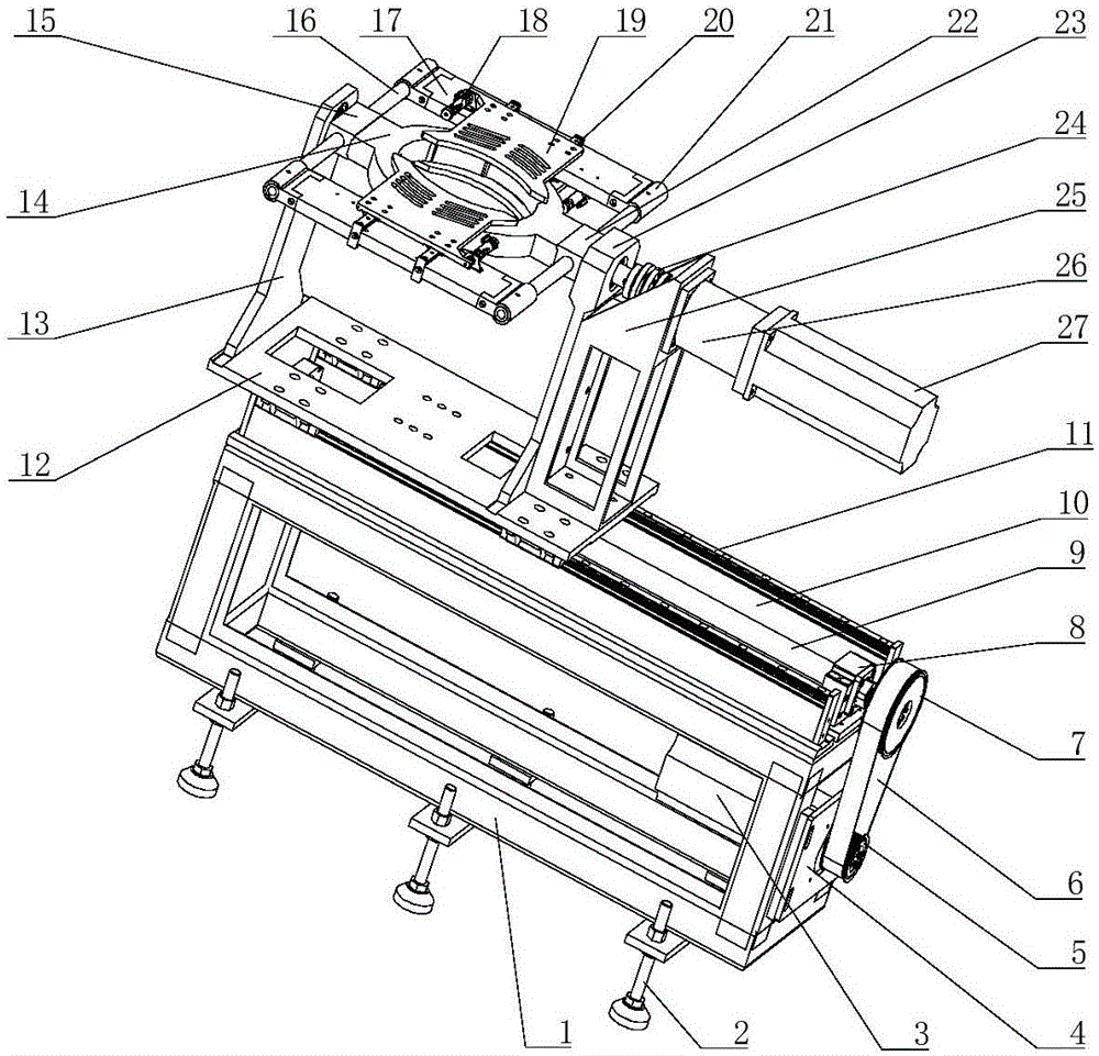
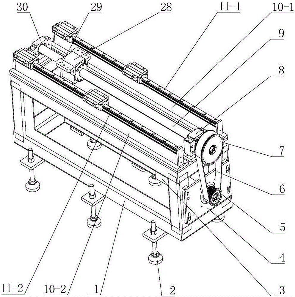
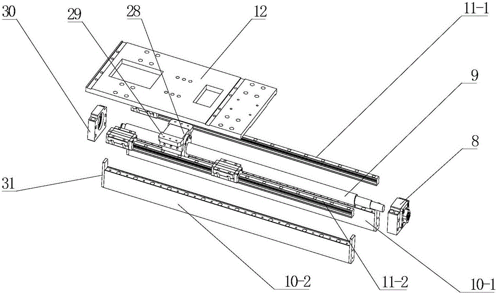
[0020] Such as figure 1 As shown, the middle turning table includes a base 1 welded by profiles, and the bottom of the base 1 is provided with an adjustable pad 2 that can effectively adjust the height of the turning table. By adjusting the nut position of the adjusting foot pad 2, the height of the middle turning table can be adjusted. One side of the base 1 is threadedly connected with a motor mounting plate 4, and the motor mounting plate 4 is provided with a vertical strip hole. By adjusting the position of the strip hole up and down, the timing belt 6 can be tensioned, and the motor mounting plate 4 is connected by bolts. There is a first servo motor 3, the output end of the first servo motor 3 is connected to the small synchronous wheel 5 through a flat key, the small synchronous wheel 5 is connected to the large synchronous wheel 7 through a synchronous belt 6, and the large synchronous wheel 7 and the ball screw 9 are also connected through Flat key connection, when th...


PUM


Abstract

The invention belongs to the technical field of mechanical processing equipment, and particularly relates to a middle roll-over table of an automatic stamping mechanical hand. When the automatic stamping mechanical hand takes out parts from an upper press, and part angle regulation needs to be carried out on a next station, a middle roll-over device is firstly regulated to a part receiving state: a positioning device is positioned below the mechanical hand, a clamping plate below the positioning plate is closed by a clamping air cylinder, a clamping plate above is opened, the mechanical hand puts the parts into the positioning device, the clamping plate above the positioning device is closed to fix the parts, the whole supporting roll-over mechanism moves to the outer part of the mechanical hand, a second servo motor works after the whole supporting roll-over mechanism is regulated to a proper position, the parts are rolled over to a needed angles, and the supporting roll-over mechanism is moved to a position below the mechanical hand through a first servo motor, so that the clamping plate above the positioning device is opened, the parts are taken away by the mechanical hand, and part roll-over transportation is completed.

Description

technical field [0001] The invention belongs to the technical field of mechanical processing equipment, and in particular relates to a turning device for workpiece turning on a stamping production line of an automatic stamping manipulator. Background technique [0002] In the traditional stamping production, the manual production method is adopted, that is, the transfer of the workpiece between the presses is performed manually, and the feeding, retrieving and turning of the workpiece are all performed manually. Now with the continuous growth of production demand, traditional production methods can no longer meet the requirements; and with the continuous development of automated manipulators, the automatic transmission of workpieces has been realized, but the flipping of workpieces is generally done manually, which is far from satisfying society. Production demand, so along with the development of modern automation manipulators, the development of the middle turning table of...

Claims


Application Information

Patent Timeline
Patent Type & Authority Applications(China)
IPC IPC(8): B21D43/00
CPCB21D43/00
Inventor 杨超君虞鹏鲁健武袁浩张清林
Owner SIYANG MINGYUXING PRECISION MACHINERY CO LTD
Why Eureka
Try Eureka