
A Gate and Container Synchronization Mechanism for High Temperature Furnace

A technology of a high-temperature furnace and a synchronizing mechanism is applied in the control of pouring molten metal from a casting ladle, metal processing equipment, casting equipment, etc. No security risk effect

Active Publication Date: 2018-09-07
东莞市镁正隆工业熔炉设备有限公司
View PDF6 Cites 0 Cited by
  • Summary
  • Abstract
  • Description
  • Claims
  • Application Information

AI Technical Summary

Problems solved by technology

[0002] In existing high-temperature furnaces, when the alloy in the crucible is melted into a liquid, the material is manually connected with a mold, just like pouring the boiling soup in the pot into the basin. This operation must be very careful, and it is not good Operation, because of artificial factors, there are various safety hazards. After the alloy is melted, the mold placed on the mold bracket is manually filled with molten alloy liquid, and then it is taken away manually, and the next mold is placed, and so on. Until The pouring is completed, and the heavy manual operation of this process makes the labor cost and production cost high and the production efficiency low

Method used


Image

  • A Gate and Container Synchronization Mechanism for High Temperature Furnace

Examples


Embodiment Construction

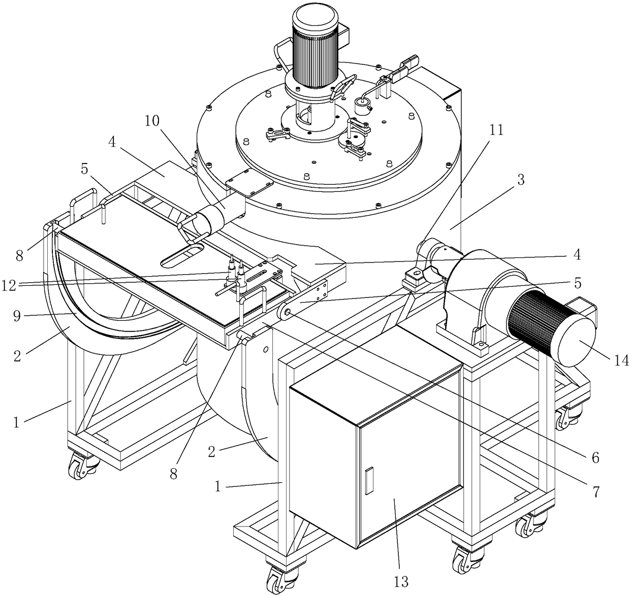
[0010] refer to figure 1 , a gate and container synchronization mechanism for high-temperature furnaces in the present invention, including two left-right symmetrical arc-shaped guide rails 2 fixed on the bottom frame 1, a support plate 4 fixed on the upper side of the high-temperature furnace body 3, supporting A synchronous arm 5 is fixedly protruded from both sides of the plate, and a mold bracket 7 is rotatably connected between the two synchronous arms through a rotating shaft 6. The rotating shaft is located inside the both sides of the mold bracket, and Sliding wheels 8 are arranged on the outside, and arc-shaped track grooves 9 are arranged on the arc-shaped guide rails. The sliding wheels are put into the arc-shaped track grooves and can slide along the arc-shaped track grooves. The frame is located directly below the gate 10 of the high-temperature melting furnace, and the two sides of the high-temperature melting furnace body are fixed with rotating shafts 11, which...


PUM


Abstract

The invention discloses a sprue and container synchronizing mechanism used for a high-temperature smelting furnace. The sprue and container synchronizing mechanism comprises two arc guiderails and a support plate, a synchronizing arm fixedly extends from each of the two sides of the support plate, a mold bracket is rotatably connected between the two synchronizing arms through a rotating shaft, the rotating shaft is located inside the two sides of the mold bracket, sliding wheels are arranged outside the two sides of the mold bracket, the arc guiderails are provided with arc rail grooves, the sliding wheels are put into the arc rail grooves and can slide along the arc rail grooves, the mold bracket is located right below a sprue, rotating shafts are fixed on the two sides of a furnace body of the high-temperature smelting furnace, the rotating shafts are rotatably connected onto an underframe, when the furnace body of the high-temperature smelting furnace rotates around the rotating shaft and inclines, the horizontal distances between any parts between the path lines of the rotating shafts and the arc rail grooves are equal to the distances from the sliding wheels to the rotating shafts. The manual receiving of materials is not needed, the automated operation is realized, no potential safety hazard exists, the labor cost is reduced, the production cost is lower, the whole process is automatically completed mechanically, and the production efficiency is higher.

Description

technical field [0001] The invention relates to auxiliary equipment for high-temperature furnaces, in particular to a gate and container synchronization mechanism for high-temperature furnaces. Background technique [0002] In existing high-temperature furnaces, when the alloy in the crucible is melted into a liquid, the material is manually connected with a mold, just like pouring the boiling soup in the pot into the basin. This operation must be very careful, and it is not good Operation, because of artificial factors, there are various safety hazards. After the alloy is melted, the mold placed on the mold bracket is manually filled with molten alloy liquid, and then it is taken away manually, and the next mold is placed, and so on. Until After the pouring is completed, the heavy manual operation of this process makes the labor cost and production cost high, and the production efficiency is low. Therefore, be necessary to research and develop a kind of new auxiliary equip...

Claims


Application Information

Patent Timeline
Patent Type & Authority Patents(China)
IPC IPC(8): B22D37/00
CPCB22D37/00
Inventor 倪红星
Owner 东莞市镁正隆工业熔炉设备有限公司
Learn More