Full-automatic sawing device with pressing function
A technology of pressing device and sawing device, which is applied in the direction of sawing machine, metal sawing equipment, manufacturing tools, etc., can solve the problem of not meeting the sawing requirements of multi-angle cutting profiles, it is difficult to ensure the neat arrangement of profiles, and the profiles are easy to move And other problems, to achieve the effect of good consistency, high sawing precision, and reduce production costs
- Summary
- Abstract
- Description
- Claims
- Application Information
AI Technical Summary
Problems solved by technology
Method used
Image

Examples
Embodiment Construction
[0021] The present invention will be further described in detail below in conjunction with the accompanying drawings and specific embodiments.
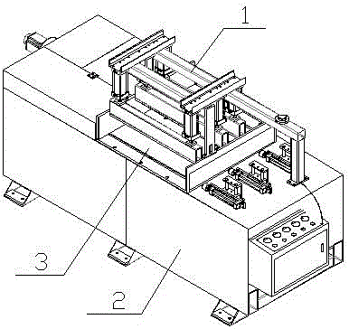
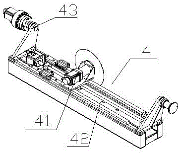
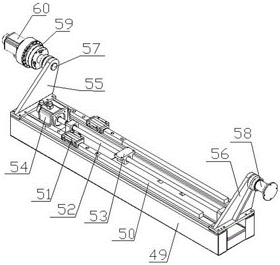
[0022] Accompanying drawing is a kind of specific embodiment of the present invention. This embodiment comprises frame 2, pressing device 1 and sawing device 4, and described frame 1 is provided with sawing workbench 3, and pressing device 1 is fixed on the sawing workbench 3, and sawing device 4 is installed In the frame 1 below the sawing workbench 3; the clamping device 1 includes a retaining clamping device 12, a horizontal clamping device 17, a left clamping device 13 and a right clamping device 14; the sawing device 4 includes a sawing mechanism 41, a feeding mechanism 42 and an angle adjustment mechanism 43, the sawing mechanism 41 is installed on the feeding mechanism 42, and the feeding mechanism 42 is installed on the angle adjustment mechanism 43.
[0023] The blocking and pressing device 12, the left pressing device 13 an...
PUM
 Abstract
Description
Claims
Application Information
 - Generate Ideas
- Intellectual Property
- Life Sciences
- Materials
- Tech Scout
- Unparalleled Data Quality
- Higher Quality Content
- 60% Fewer Hallucinations
Browse by: Latest US Patents, China's latest patents, Technical Efficacy Thesaurus, Application Domain, Technology Topic, Popular Technical Reports.
© 2025 PatSnap. All rights reserved.Legal|Privacy policy|Modern Slavery Act Transparency Statement|Sitemap|About US| Contact US: help@patsnap.com