Positioning device for assembly

A technology of positioning device and assembly, applied in the direction of grinding workpiece supports, honing machine tools, metal processing equipment, etc., can solve the problems of low coaxiality accuracy, and achieve the effect of improving coaxiality accuracy

Active Publication Date: 2017-05-10
CHINA HANGFA SOUTH IND CO LTD
View PDF6 Cites 2 Cited by
  • Summary
  • Abstract
  • Description
  • Claims
  • Application Information

AI Technical Summary

Problems solved by technology

[0004] The invention provides an assembly positioning device to solve the technical problem of low coaxiality accuracy in the prior combined processing and positioning of starters

Method used


Image

  • Positioning device for assembly
  • Positioning device for assembly

Examples


Embodiment Construction

[0029] It should be noted that, in the case of no conflict, the embodiments in the present application and the features in the embodiments can be combined with each other. The present invention will be described in detail below with reference to the accompanying drawings and examples.

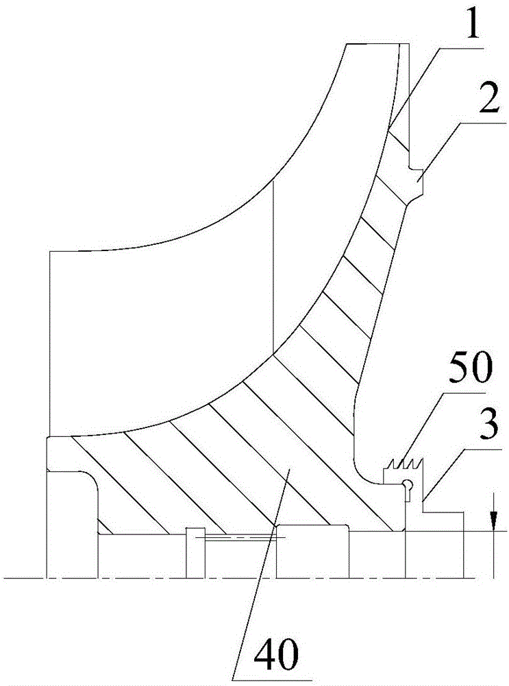
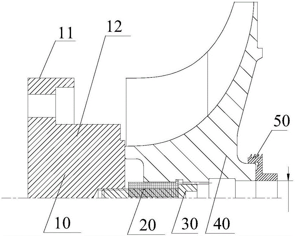
[0030] refer to figure 2 , the preferred embodiment of the present invention provides an assembly positioning device, the assembly includes a reference piece and a workpiece to be processed with an interference fit with the reference piece, the assembly positioning device is used for positioning the assembly during processing, and is easy to treat The inner hole of the workpiece is ground, and the assembly positioning device includes: a body 10 for fixing the assembly, two semi-annular opening bushings 20 that are clearance-fitted with the center hole of the reference piece, and a set for the reference piece. The fixing part 30 positioned in the central hole, the fixing part 30 stretches the ...


PUM


Abstract

The invention discloses a positioning device for an assembly. The device is used for positioning during machining of the assembly; the assembly comprises a reference piece and a to-be-machined piece in interference fit with the reference piece; the positioning device comprises a body for fixing the assembly, two semi-circular open bushings in clearance fit with the central hole of the reference piece and a fixing piece for fixing the central hole of the reference piece; and the fixing piece penetrates through the central hole of the reference piece to expand the two semi-circular open bushings to be a full ring, so that the assembly is pressed against the body. The stressed part of the positioning device is far away from the machined part of the to-be-machined piece, so that the machined part of the to-be-machined piece is located in a non-stressed area and is affected by grinding resistance only, and the coaxial accuracy of the positioning device is improved; and the technical problem that the coaxial accuracy is reduced due to deformation of machined parts due to the fact that stressed parts are close to the machined parts during machining positioning of existing starter type assemblies is solved.

Description

technical field [0001] The invention relates to the field of starter component manufacturing, in particular to an assembly positioning device. Background technique [0002] The starter centrifugal impeller combination includes the centrifugal impeller and the grate ring. The centrifugal impeller and the grate ring have an interference fit and the matching surface is narrow, such as figure 1 As shown, when grinding the inner hole of the grate ring, one method is to fix the end face of the centrifugal impeller, such as figure 1 The first stress point 1 and the second stress point 2, but the end face of the centrifugal impeller has an anodized film layer, if the film layer is under pressure, it will be damaged. Another method is to directly compress the grate ring end face, such as figure 1 The third stress point 3 in the center is close to the processing part. After the inner hole of the grate ring is processed, loosening the pressing device will cause the deformation of the...

Claims


Application Information

Patent Timeline
Patent Type & Authority Applications(China)
IPC IPC(8): B24B33/02B24B41/06
CPCB24B33/02B24B41/06
Inventor 刘海根陈金灿张永辉
Owner CHINA HANGFA SOUTH IND CO LTD
Why Eureka
Try Eureka