Automatic material change device for bobbin case storage tray

A storage tray, automatic technology, applied in auxiliary devices, bobbin winding in sewing machines, mechanism of embroidery machines, etc.

Inactive Publication Date: 2019-10-22
ZHUJI LIGHT IND TIMES ROBOT TECH CO LTD
View PDF2 Cites 1 Cited by
  • Summary
  • Abstract
  • Description
  • Claims
  • Application Information

AI Technical Summary

Problems solved by technology

[0004] There are currently two key technical issues that need to be solved urgently for the spare bobbin case automatic feeding device: (1) It is necessary to be able to accurately transport the spare bobbin case to a position close to the bobbin case replacement device for a long distance to replenish the spare bobbin case, thereby Let the operator only need to refill the bobbin case on the spare bobbin case automatic feeding device on the edge of the operation table

Method used


Image

  • Automatic material change device for bobbin case storage tray
  • Automatic material change device for bobbin case storage tray
  • Automatic material change device for bobbin case storage tray

Examples


Embodiment 1

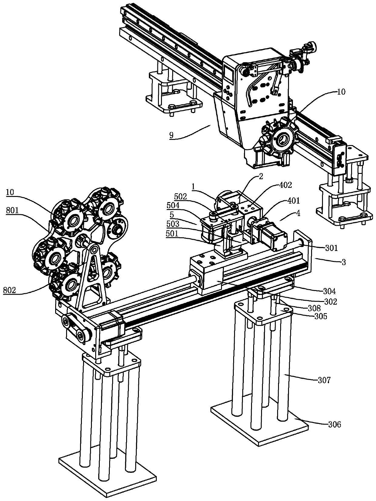
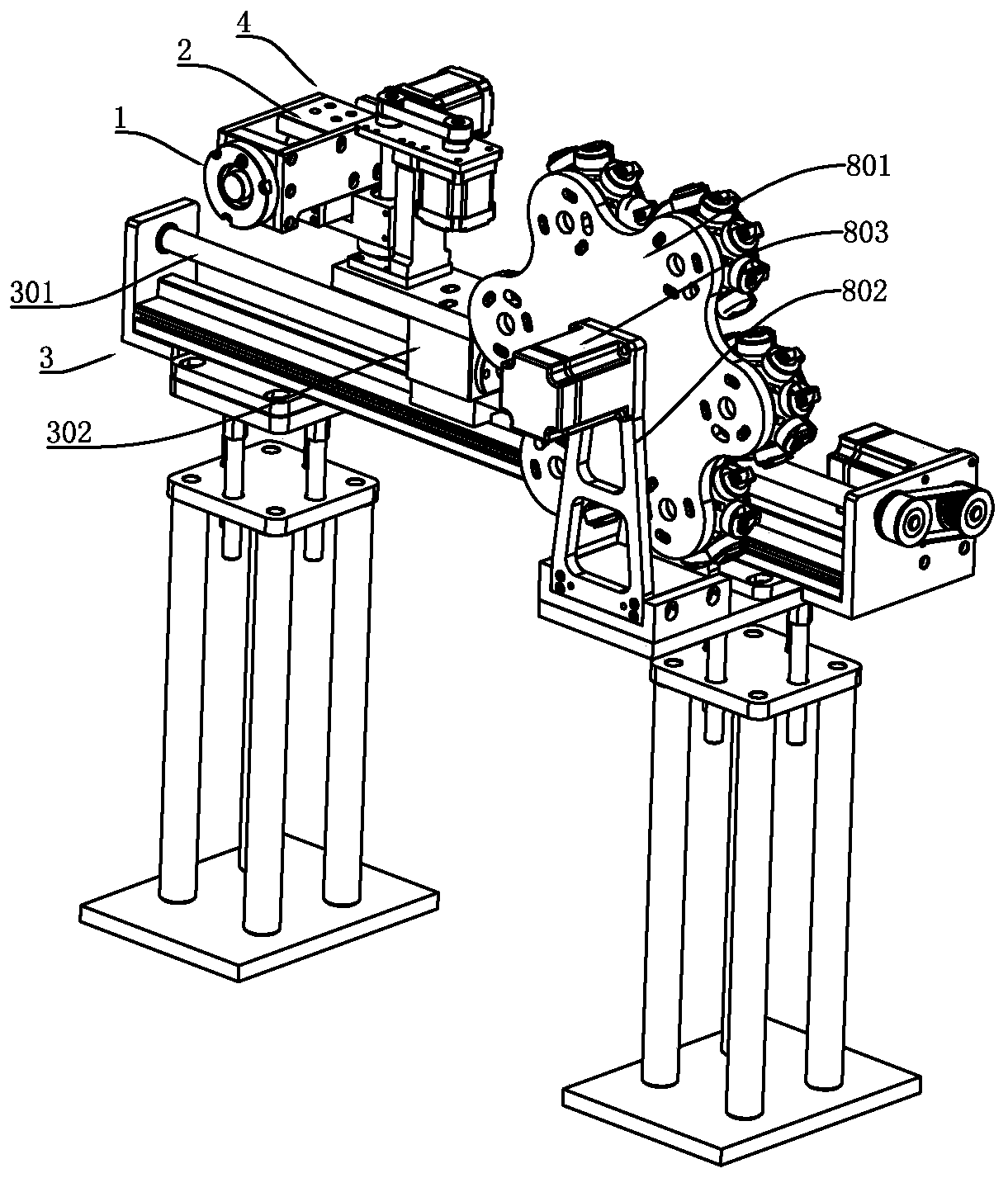
[0048] like figure 1 , figure 2 As shown, a bobbin case storage tray automatic refueling device of the present invention includes a retrieving head 1 , a floating mechanism 2 , an adjusting mechanical arm and a conveying mechanism 3 .

[0049] The adjusting mechanical arm includes a lateral movement adjustment arm 4 and a lifting height adjustment arm 5 of a lateral movement reclaiming mechanism. Under the action, the traversing direction of the traversing adjusting arm 4 is deflected, and the adjusting mechanical arm is slidably connected to the conveying mechanism 3 , and the adjusting mechanical arm and the conveying mechanism 3 are used to adjust the spatial position of the picking head 1 .

[0050] The conveying mechanism 3 includes a conveying screw guide rail 301 and a conveying sliding seat 302 , the conveying sliding seat 302 is slidably connected to the conveying screw guide rail 301 , and an adjusting mechanical arm is arranged on the conveying sliding seat 302 . ...

Embodiment 2

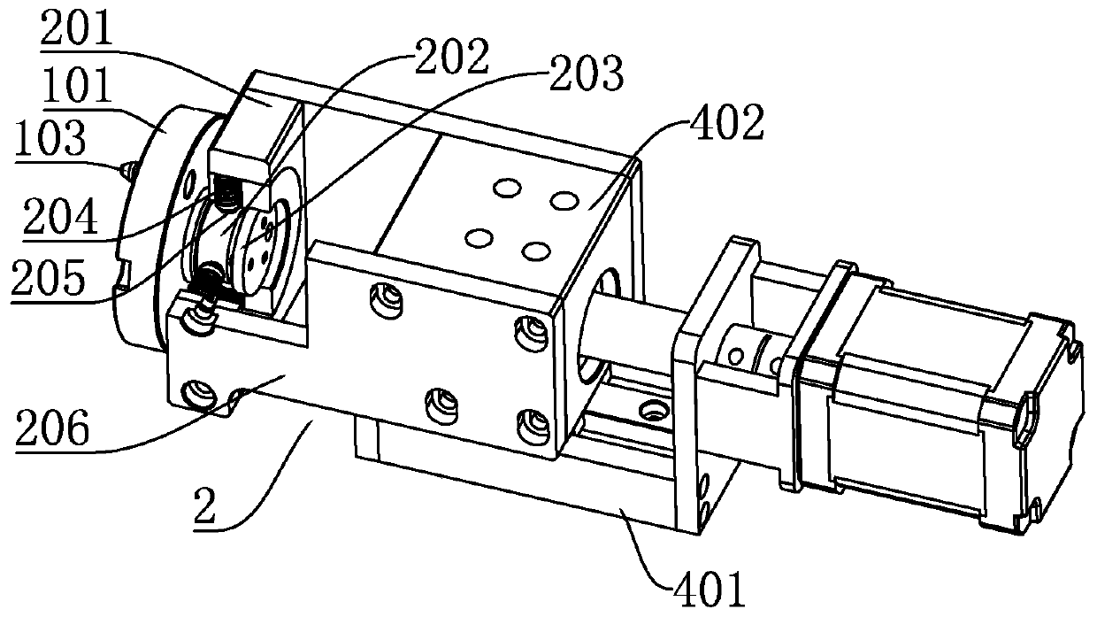
[0070] The specific structure of the floating mechanism 2 in this application can adopt alternative schemes. The biggest difference between this embodiment and the above-mentioned embodiment 1 is that the floating mechanism 2 with the following mechanism is adopted.

[0071] like Figure 5 , Image 6 As shown, the floating mechanism 2 includes a connecting frame and an elastic reset member, the connecting frame is connected to the traverse adjustment arm 4, and the picking head 1 is movably connected to the connecting frame so that the picking head 1 can move obliquely relative to the connecting frame, and the connecting frame A number of elastic return parts are arranged between the reclaimer 1 and the reclaimer 1. When the reclaimer 1 can be deflected relative to the lateral movement direction of the traversing adjustment arm 4 under the action of an external force, the elastic reset members exert elasticity on the reclaimer 1. Reset force.

[0072] The connecting frame in...

Embodiment 3

[0075] The specific structure of the floating mechanism 2 in this application can adopt alternative schemes. The biggest difference between this embodiment and the above-mentioned embodiment 1 is that the floating mechanism 2 with the following mechanism is adopted.

[0076] like Figure 7 , Figure 8 As shown, the floating mechanism 2 includes a connecting frame and an elastic reset member, the connecting frame is connected to the traverse adjustment arm 4, and the picking head 1 is movably connected to the connecting frame so that the picking head 1 can move obliquely relative to the connecting frame, and the connecting frame A number of elastic return parts are arranged between the reclaimer 1 and the reclaimer 1. When the reclaimer 1 can be deflected relative to the lateral movement direction of the traversing adjustment arm 4 under the action of an external force, the elastic reset members exert elasticity on the reclaimer 1. Reset force.

[0077] The connecting frame i...


PUM


Abstract

The invention discloses a change device for a bobbin case storage tray. The device structurally comprises a material taking head, a floating mechanism, an adjusting manipulator and a conveying mechanism, a plurality of adjusting arms are sequentially connected to form the adjusting manipulator which at least comprises a horizontal movement adjusting arm of a horizontal movement material taking mechanism and a height adjusting arm for adjusting heights and directions, the material taking head is movably connected with the horizontal movement adjusting arm through the floating mechanism and candeflect relative to the horizontal movement direction of the height adjusting arm under the action of external force, the adjusting manipulator is slidably connected with the conveying mechanism, andthe adjusting manipulator and the conveying mechanism are used for adjusting the spatial position of the material taking head. The bobbin case storage tray on an automatic embroidery machine bobbin case change device can be automatically replaced, butt joint errors in butt joint of the bobbin case storage tray and a drive shaft assembly can be adaptively compensated, and the storage tray can be accurately mounted on the drive shaft assembly for the bobbin case storage tray.

Description

technical field [0001] The invention relates to the technical field of automatic bobbin thread changing for embroidery machines, in particular to an automatic material changing device for a spare bobbin case storage tray. Background technique [0002] At present, the computer embroidery machine bobbin case automatic replacement technology is a key technical means to replace the manual replacement of the bobbin case bottom thread, shorten the downtime of the multi-station computer embroidery machine for bobbin thread replacement, improve the work efficiency of the computer embroidery machine, and finally realize the fully automated production of machine replacement. . The bottom thread of computerized embroidery machine is composed of bobbin case and bobbin. When the embroidery machine runs out of bottom thread, it needs to replace the bobbin case (bobbin). The device is equipped with a bobbin case replacement mechanism (such as a mechanical finger mechanism) to complete the...

Claims


Application Information

Patent Timeline
Patent Type & Authority Applications(China)
IPC IPC(8): D05C11/18D05C13/06D05B59/04
CPCD05B59/04D05C11/18D05C13/06
Inventor 徐海苗
Owner ZHUJI LIGHT IND TIMES ROBOT TECH CO LTD
Why Eureka
Try Eureka