Power-driven roller coaster chassis system

A power-driven, roller coaster technology, applied in the field of amusement and entertainment equipment, can solve the problems of increasing the track design, manufacturing difficulty, limit the radius of the running track curve, disadvantageous roller coaster operation economy, etc. Passability and the effect of improving resource utilization

Active Publication Date: 2020-11-06
BEIJING SHIBAOLAI AMUSEMENT EQUIP
View PDF5 Cites 1 Cited by
  • Summary
  • Abstract
  • Description
  • Claims
  • Application Information

AI Technical Summary

Problems solved by technology

[0003] Most of the power-driven roller coasters in the prior art are realized by simply adding a driving device on the basis of the traditional roller coaster structure, which will cause the chassis size of the car body to be too large, resulting in a large turning radius of the vehicle, and the running track has a very large curve radius in the horizontal and vertical directions. Large restrictions, especially in the limited indoor space, it is difficult to design and manufacture more interesting running tracks
At the same time, since the additional driving device generally only has the function of acceleration and deceleration, and lacks an active change of direction device, resulting in additional resistance at the turning point of the running track, the driving power must be increased, which is not conducive to the operating economy of the roller coaster, and the additional driving The device also needs to add a special driving track with different curvature changes in addition to the original running track, which greatly increases the difficulty of track design and manufacture

Method used


Image

  • Power-driven roller coaster chassis system
  • Power-driven roller coaster chassis system
  • Power-driven roller coaster chassis system

Examples


Embodiment Construction

[0025] In order to understand the content of the present invention more clearly, it will be described in detail with reference to the drawings and embodiments.

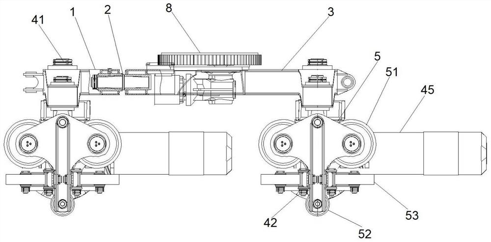
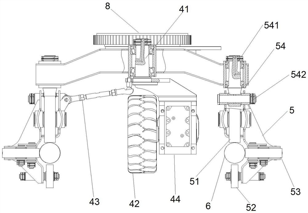
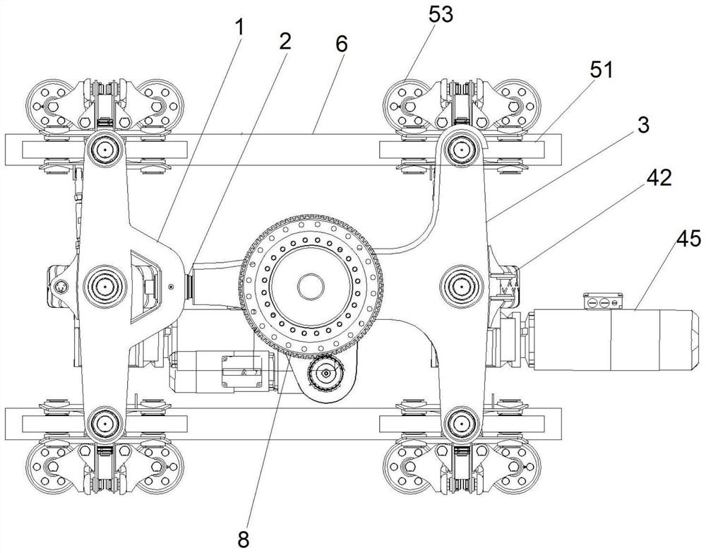
[0026] Such as Figure 1 to Figure 6 A preferred embodiment of the power-driven roller coaster chassis system of the present invention is shown as shown, including a front axle 1, a rear axle 3 connected to the front axle 1 through a swivel pair 2 in a single-degree-of-freedom axis, and mounted on the front axle 1 respectively. and a total of two sets of drive assemblies 4 in the center of the rear axle 3, and a total of four sets of wheel assemblies 5 installed on both sides of the front axle 1 and the rear axle 3, and preferably also include a cockpit installed on the rear axle 3 The rotating assembly 8 is composed of a slewing support tray and a seat motor that drives the slewing support tray to rotate to provide the autorotation function of the seat relative to the vehicle. After the front axle 1 and the rear axl...


PUM


Abstract

The invention relates to a power-driven roller coaster chassis system. A driving device in linkage steering with a wheel set assembly is used for dispersedly driving a vehicle to realize the synchronous curvature of a driving track and a running track; the climbing and braking capacity of the vehicle is improved, meanwhile, the vehicle body structure can be optimized, the turning radius of the vehicle in the horizontal direction and the vertical direction is reduced, the overall occupied area of equipment is reduced, the space utilization rate is increased, and the equipment competitiveness isenhanced.

Description

technical field [0001] The invention relates to the technical field of amusement and entertainment equipment, in particular to a power-driven roller coaster chassis system. Background technique [0002] As a kind of amusement equipment, the roller coaster is loved by many people, especially the new integrated power-driven roller coaster equipment that integrates the traditional roller coaster, self-driven car body, multimedia interaction and indoor and outdoor sound and light effects is gradually favored by tourists. It is a major amusement equipment. Direction of development. [0003] Most of the power-driven roller coasters in the prior art are realized by simply adding a driving device on the basis of the traditional roller coaster structure, which will cause the chassis size of the car body to be too large, resulting in a large turning radius of the vehicle, and the running track has a very large curve radius in the horizontal and vertical directions. Large restrictions...

Claims


Application Information

Patent Timeline
Patent Type & Authority Applications(China)
IPC IPC(8): A63G7/00
CPCA63G7/00
Inventor 韩金锋
Owner BEIJING SHIBAOLAI AMUSEMENT EQUIP
Why Eureka
Try Eureka