Power generation method and system equipped with energy storage and energy release accommodation mechanism

a technology of energy storage and accommodation mechanism, which is applied in the direction of mechanical energy handling, dynamo-electric components, ac network load balancing, etc., to achieve the effect of large fall head

Active Publication Date: 2022-03-03
INFINIFORCE INC
View PDF0 Cites 1 Cited by
  • Summary
  • Abstract
  • Description
  • Claims
  • Application Information

AI Technical Summary

Benefits of technology

[0004]An objective of the invention is to provide a power generation system that utilizes the energy storage and energy release accommodation mechanism arranged in the system to provide self-operation of the system and provide electric energy to external load. Especially refers to a multi-level flywheel linkage system composed of energy storage unit, energy release unit, variable speed gear unit, power generation unit, electric power storage unit and electric circuit modulation unit, etc. There are multi-level flywheel groups arranged in the system, which are basically divided into driving master wheel, driven accommodation wheel and output wheel. When the driving master wheel is driven by mechanical energy to reach a rated rotating speed, and the maximum energy in the system is stored, the driving master wheel that stores the largest inertia in the system transfers energy to the driven accommodation wheel. According to the system itself and the scale of the load, the driven accommodation wheel can be concurrently served by the driving master wheel, or it can be one or m

Problems solved by technology

However, if the energy output is large, or sometimes large and sometimes small resulting in a large fall head, that is, when the power generated by the generator supplies a large load, more accom

Method used


Image

  • Power generation method and system equipped with energy storage and energy release accommodation mechanism
  • Power generation method and system equipped with energy storage and energy release accommodation mechanism

Examples


Embodiment Construction

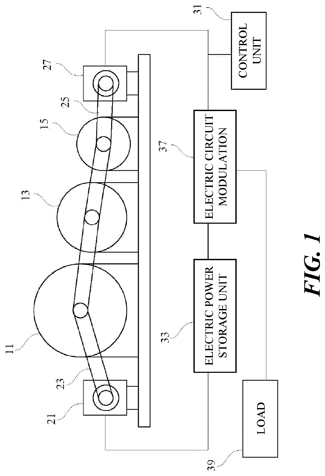
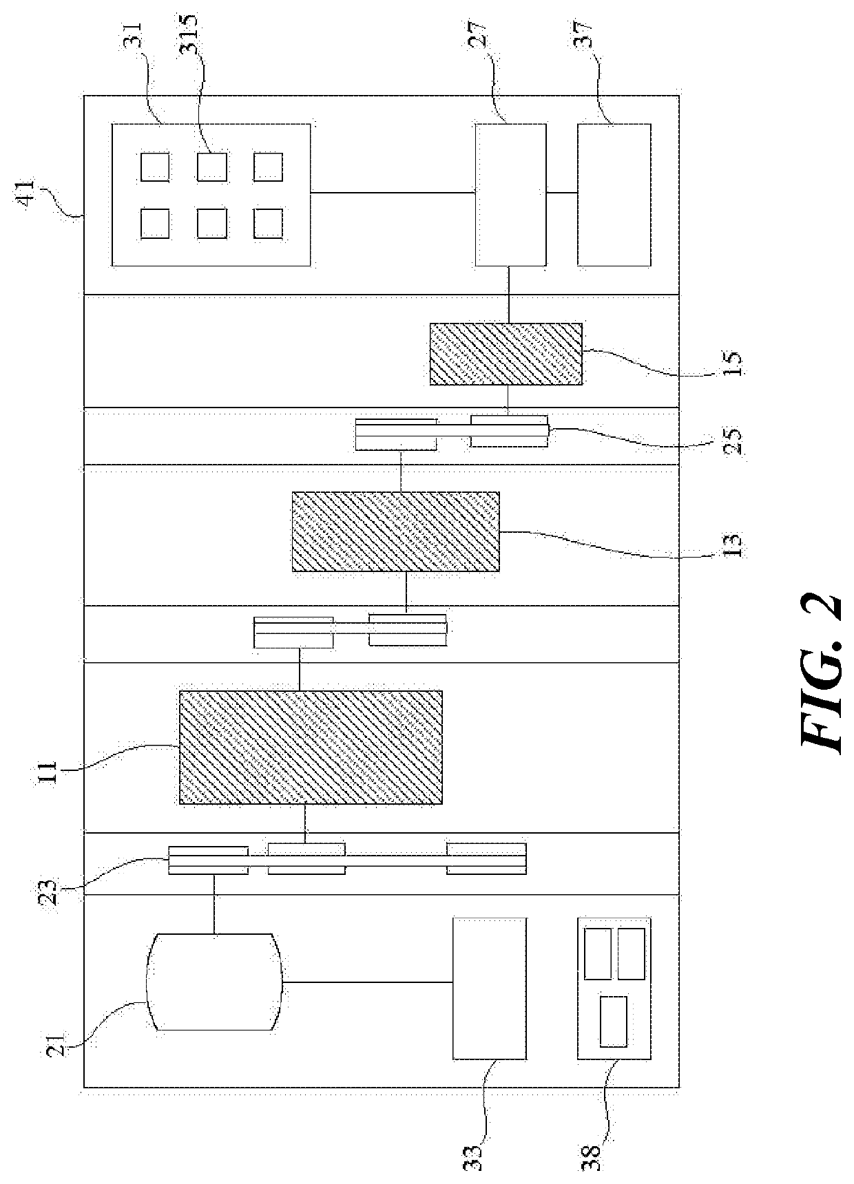
[0012]Please refer to FIG. 1, which is a structural schematic diagram of an embodiment of an energy storage system equipped with an energy storage and energy release accommodation mechanism according to the present invention. The energy storage system of the invention is equipped with a driving master wheel 11, a driven accommodation wheel 13, and an output wheel 15. Among them, the driving master wheel 11 is driven by a prime mover 21 with a transmission unit 23 such as a belt, and the generator 27 is driven by the output wheel 15 with another transmission unit 25 such as a belt.

[0013]In an embodiment of the present invention, after the built-in control unit 31 of the system issues a start-up instruction, the prime mover 21 obtains the electric energy provided by an electric power storage unit 33, and thus generates a mechanical energy. The mechanical energy generated by the prime mover 21 slowly pulls the driving master wheel 11 to start to rotate via a transmission unit 23 such a...


PUM


Abstract

The invention provides a power generation method and a system equipped with energy storage and energy release accommodation mechanism. By using an energy storage and energy release accommodation system arranged in the system, the generator set at an end of the system can immediately supplement energy from an energy storage unit after providing electric energy to a load, so that the output energy will not drop suddenly, while still stably maintaining both the rated energy output and the system operation.

Description

BACKGROUND OF THE INVENTION1. Field of the Invention[0001]The invention relates to a power generation method and system equipped with energy storage and energy release accommodation mechanism.2. Description of the Prior Art[0002]For many years, most of the developers engaged in flywheel auxiliary power generation only use flywheel units to store energy. However, when the flywheel is switching-on the load, the inertia stored in the flywheel will also be released immediately, resulting in a rapid drop in rotating speed, so no real successful case has been seen.[0003]In view of this, the present invention provides an energy storage system and method equipped with energy storage and energy release accommodation mechanism, so that the generator set at the end of the system can immediately supplement energy from the energy storage unit after providing electric energy to the load. It is the objective of the invention to prevent the output energy from dropping suddenly, while still stably m...

Claims


Application Information

Patent Timeline
IPC IPC(8): H02K7/02H02K7/20
CPCH02K7/025H02K7/20H02K53/00H02K7/116H02J3/32H02J7/35
Inventor LIAO, MING-CHEN
Owner INFINIFORCE INC
Why Eureka
Try Eureka