Automatic photographing robot

An automatic camera and robot technology, applied in manipulators, program-controlled manipulators, optical testing flaws/defects, etc., can solve problems such as difficult to ensure effective driving, troublesome operation, and inability to ensure effective pressure stability

Active Publication Date: 2016-01-27
NANJING UNIV OF SCI & TECH
View PDF5 Cites 1 Cited by
  • Summary
  • Abstract
  • Description
  • Claims
  • Application Information

AI Technical Summary

Problems solved by technology

However, the preload of its structure uses a compression spring, which cannot ensure the effective pressure on the barrel under any caliber is stable, and it is even more difficult to ensure effective driving.
In addition, the applicable range of the barrel di...

Method used


Image

  • Automatic photographing robot
  • Automatic photographing robot
  • Automatic photographing robot

Examples


Embodiment Construction

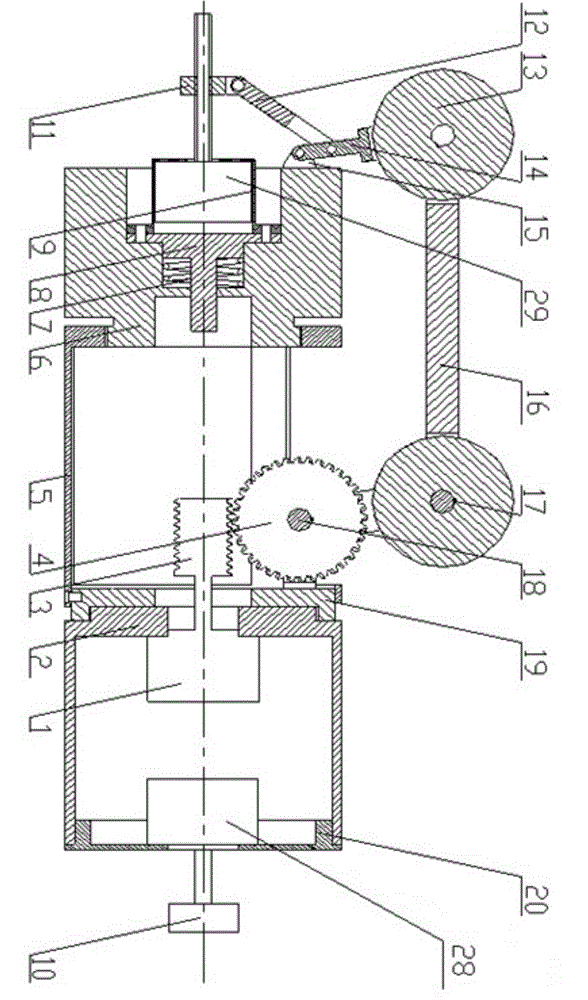
[0029] The present invention will be described in further detail below in conjunction with the accompanying drawings.

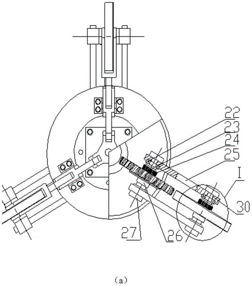
[0030] combine figure 1 and image 3 , an automatic camera robot, comprising a frame 5, a drive mechanism, a variable diameter adjustment mechanism, a camera mechanism, a transmission mechanism, a walking mechanism and an automatic control system, the two ends of the frame 5 are hollow cylinders, the diameter of the cylindrical hole at one end is φ60mm, and the other end The diameter of the cylindrical hole is φ82mm, and the two cylinders are connected by three connecting rods evenly distributed along the circumference of the cylinder. The driving mechanism is connected with the bolt of the φ82mm cylindrical hole of the frame 5, and the variable diameter adjustment mechanism is connected with the threaded connection of the φ60mm cylindrical hole of the frame 5. Take a photo The mechanism is connected with the driving mechanism, the transmission mechanism is ...


PUM


Abstract

The invention discloses an automatic photographing robot, comprising a rack, a drive mechanism, a variable diameter adjusting mechanism, a photographing mechanism, a transmission mechanism, a running gear, and an automatic control system. Three stepping motors can be used to drive the robot and control size of expanded pipe diameters and rotation of a camera. The robot realizes tasks of walking, going back, stopping, and taking pictures in different diameter pipes. The drive mechanism uses a worm and gear mechanism and a synchronous pulley mechanism, and can realize constant transmission ratio and stable motion transmission. The running gear uses three-jaw form centring, and uses a parallelogram mechanism to realize same-degree diameter variation at the same time of walking wheels in three groups of walking devices. A variable diameter adjusting device uses a screw-nut mechanism to adjust expanded diameter sizes. In addition, a built-in flexible regulation device can overcome stuck phenomenon in a walking process. The robot is simple in structure and convenient in manufacturing, and the robot can ensure very high coaxiality precision.

Description

technical field [0001] The invention belongs to the field of barrel detection, and in particular relates to an automatic camera robot. Background technique [0002] Most of the current bore inspections still use the traditional sight glass composed of optical telescopic systems for naked eye observation, and then rely on expert experience to make observations and judgments to determine the level of damage and repair in the bore. This approach relies primarily on subjective judgments rather than objective criteria. Therefore, the measurement results have low accuracy and large errors, and it is difficult to adapt to modern artillery production technology. It is conceivable that if a device is designed to automatically complete the process of bore information detection, and then the detected information is processed by a computer system and a series of algorithms, so as to combine the measured high-precision data with the objectively established internal bore information. Co...

Claims


Application Information

Patent Timeline
IPC IPC(8): B25J9/08B25J19/04G01N21/88
Inventor 葛建立熊伟张鸿浩季宇雷孙全兆王飞杨国来徐锐
Owner NANJING UNIV OF SCI & TECH
Why Eureka
Try Eureka