Back air filling device of tire

An inflatable device and tire technology, applied in tires, transportation and packaging, vehicle maintenance, etc., can solve the problems of tire shaping accuracy, poor coaxiality, and easy deformation of tires, and achieve simple structure, low cost, and coaxiality. High precision effect

Active Publication Date: 2014-02-05
SINO ARP TIRES EQUIP TECH (SUZHOU) CO LTD
View PDF5 Cites 0 Cited by
  • Summary
  • Abstract
  • Description
  • Claims
  • Application Information

AI Technical Summary

Problems solved by technology

When the tire is clamped on the upper and lower chucks, due to the poor coaxiality of the upper and lower pallets, the tire's shaping accuracy will be affected, and the tire is prone to deformation

Method used


Image

  • Back air filling device of tire
  • Back air filling device of tire
  • Back air filling device of tire

Examples


Embodiment 1

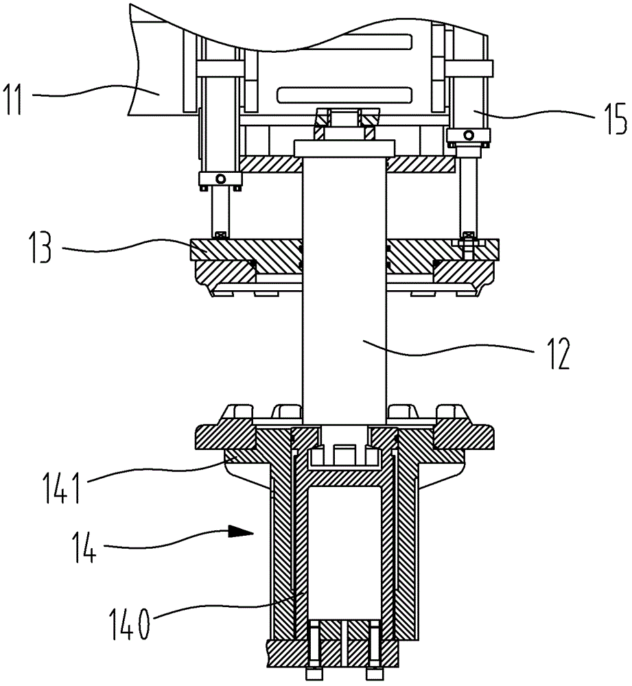
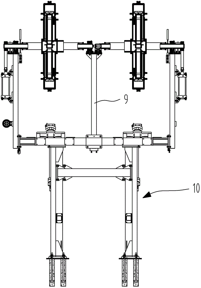
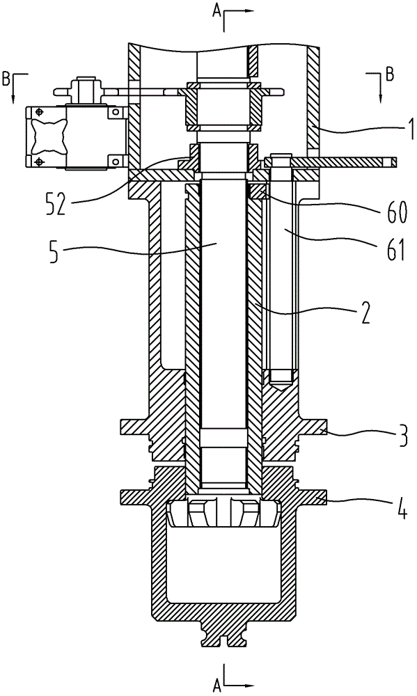
[0055] Embodiment one: see figure 2 with image 3 As shown, a tire rear inflation device includes a support beam 1, a locking rod 2, a center rod 5, a column 9, four stations and two lifting devices 10, the center rod 5 is supported on the support beam 1, and the upper The tray 3 and the lower tray 4 are coaxially arranged, and each station includes an upper tray 3, a lower tray 4 and a locking bar 2, the upper tray 3 and the upper chuck together constitute an upper chuck assembly, and the lower tray 4 and the lower tray The lower chucks form the lower chuck assembly together, and the tire is clamped between the upper and lower chucks when finalizing the shape.

[0056] The left and right sides of the column 9 are respectively provided with two stations, and the two stations located on the same side of the column 9 are respectively arranged on the upper and lower sides of the support beam 1 and share the support beam 1 .

[0057] The left and right sides of the column 9 are...

Embodiment 2

[0083] Embodiment 2: The structure of this embodiment is basically the same as that of Embodiment 1, the difference is: as Figure 14 As shown, the drive mechanism 7 is a chain transmission, including a motor 73, a chain 74, a driving sprocket 75 and a driven sprocket 76 engaged with the chain 74, the motor 73 is fixed on the support beam 1, and the driving The sprocket 75 is fixed on the output shaft of the motor 73, and the driven sprocket 76 is fixed on the positioning end 51 of the central rod.


PUM


Abstract

A tire post-inflation device comprises a support beam (1), a locking rod (2), a center rod (5), an upper tray (3) and a lower tray (4) coaxially disposed; the upper tray (3) is sleeved on the locking rod (2); the upper end of the upper tray (3) is fixedly connected to the support beam (1); the center rod (5) is provided with an engagement end (50) and a positioning end (51) thereon; the non-locking end of the locking rod (2) is provided with an axially threaded hole; the engagement end (50) is provided with external threads thereon; the locking rod (2) forms a screw transmission with the center rod (5) by utilizing the screwable connection between the threaded hole and the engagement end (50); the locking rod (2) axially reciprocates via the rotation and the screw transmission of the center rod (5). The device utilizes the up and down reciprocation of the locking rod (2) to adjust the rim width; the upper tray (3) is fixed on the support beam (1), is stationary in the whole working process of the post-inflation device, and is coaxial with the lower tray (4) with a high precision, such that the tire is unlikely to deform.

Description

technical field [0001] The invention relates to a tire post-inflation device, which is used for shaping and cooling the tire after vulcanization. Background technique [0002] At present, most of the post-inflation devices of domestic tire shaping vulcanizers use the position of the upper chuck or the lower chuck to determine the rim width that meets the specifications of the tire to be shaped. [0003] Such as figure 1 The tire rear inflation device shown includes a support beam 11, a locking bar 12, an upper tray 13 and a lower tray 14 arranged coaxially, the upper tray and the upper chuck together constitute an upper chuck assembly, and the lower tray and the upper chuck The lower chucks together constitute the lower chuck assembly, the locking rod 12 is fixed on the support beam 11, the upper tray 13 is sleeved on the locking rod 12; the lower tray 14 is sleeved on the inner disc seat 140 and The outer disc seat 141 on the top is formed, and the screw transmission is f...

Claims


Application Information

Patent Timeline
Patent Type & Authority Patents(China)
IPC IPC(8): B29C35/16B29L30/00
CPCB60S5/043
Inventor 张正罗
Owner SINO ARP TIRES EQUIP TECH (SUZHOU) CO LTD
Why Eureka
Try Eureka