Fabric compounding device

A composite device and fabric technology, applied in lamination devices, layered products, lamination, etc., can solve problems such as deficiencies, and achieve the effects of reasonable overall structure, guaranteed quality, and good stability

Active Publication Date: 2017-05-10
嘉兴市大钇纺织科技股份有限公司
View PDF2 Cites 3 Cited by
  • Summary
  • Abstract
  • Description
  • Claims
  • Application Information

AI Technical Summary

Problems solved by technology

Although the current fabric compounding equipment can also complete the compounding of double (multi-layer) composite fa

Method used


Image

  • Fabric compounding device
  • Fabric compounding device
  • Fabric compounding device

Examples


Embodiment 1

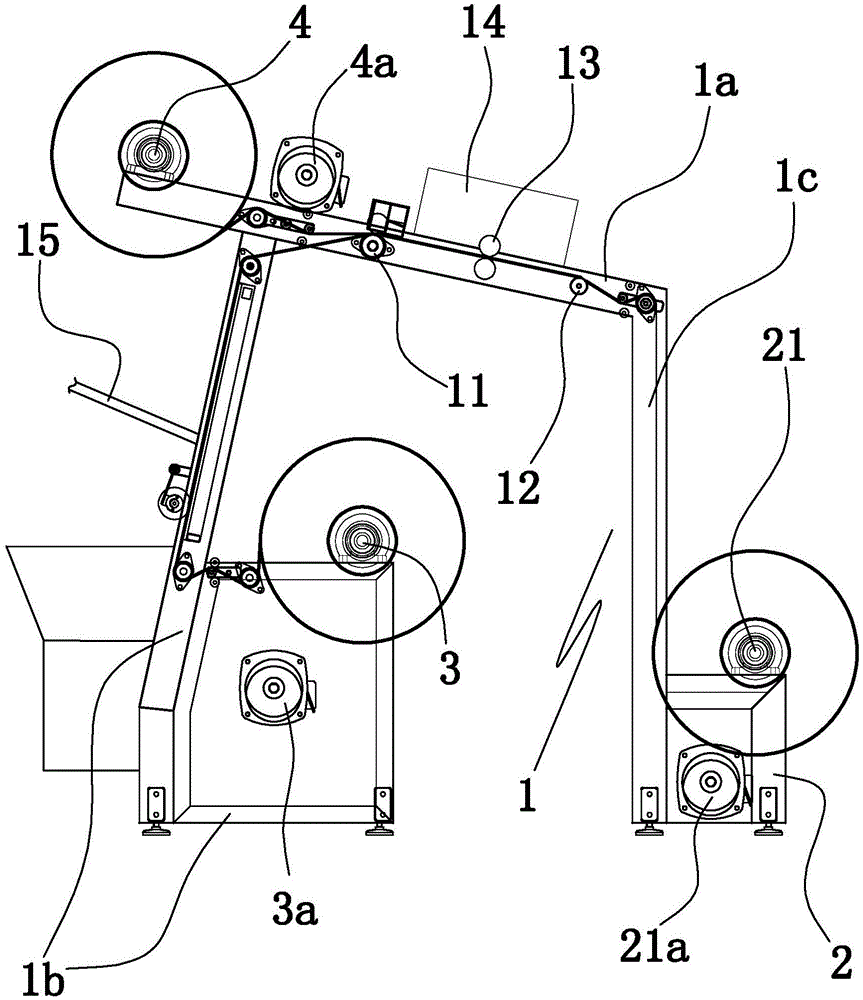
[0025] Embodiment 1: as figure 1 In the shown embodiment, a fabric compounding device includes a main frame 1, a finished material winding roller 21, a winding motor 21a for driving the finished material winding roller to rotate, and a lower layer feeding roller 3 wound with a lower layer of fabric And the upper layer feed roller 4 that is wound with upper layer fabric, described main frame is provided with the lower motor 3a that is used to drive the lower layer feed roller to rotate and the upper layer motor 4a that is used to drive the upper layer feed roller to rotate, and main frame is provided with material forming part , the material forming part includes the first shaping single roller 11, the second shaping single roller 12 and an ultrasonic welding machine 14 for compositely connecting each layer of fabric;

[0026] The ultrasonic welding machine is located between the first shaping single roller and the second shaping single roller. The main frame is equipped with a...

Embodiment 2

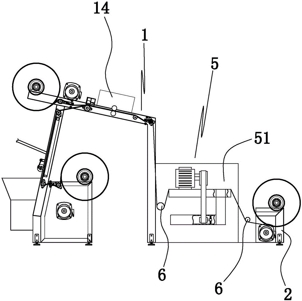
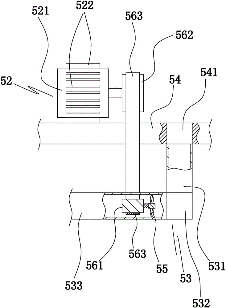
[0030] Embodiment 2: the basic structure and implementation mode of this embodiment are the same as embodiment 1, and its difference is, as Figure 2 to Figure 5 As shown in , there are two self-adjusting mechanisms 5 between the main frame and the winding frame, an adjusting transition roller 6 is arranged between the main frame and the two self-adjusting mechanisms, and the winding frame and the two self-adjusting mechanisms There is an adjustment transition roller between them, and two self-adjusting mechanisms are symmetrically arranged along a symmetrical plane, and the axis of the main roller for inspection is perpendicular to the said symmetrical plane. The air guide impeller 55, the air suction pipe 53 arranged on the adjustment frame and the fabric guide plate 54 used to stick to the bottom surface of the fabric to support the fabric, the axis of the cloth pulling wheel is horizontal and perpendicular to the axis of the main inspection roller;

[0031] In a self-adjus...


PUM


Abstract

The invention discloses a fabric compounding device, which comprises a main machine frame, a formed material rolling roller, a rolling motor, a lower layer feeding roller and an upper layer feeding roller, wherein the rolling motor is used for driving the formed material rolling roller to rotate; lower layer fabrics are rolled on the lower layer feeding roller; upper layer fabrics are rolled on the upper layer feeding roller; a lower layer motor used for driving the lower layer feeding roller to rotate and an upper layer motor used for driving the upper layer feeding roller to rotate are arranged on the main machine frame; a material forming part is arranged on the main machine frame, and comprises a first shaping single roller, a second shaping single roller and an ultrasonic welding machine used for compounding and connecting all layers of fabrics; the ultrasonic welding machine is positioned between the first shaping single roller and the second shaping single roller. The fabric compounding device has the beneficial effects that the integral structure is reasonable; a conveying structure, a compounding structure and a coiling structure are used, so that the continuous material compounding can be realized; the shaping action is performed before the compounding; the compounding efficiency is high; the stability of the material forming process is good; the quality of the formed material can be guaranteed.

Description

technical field [0001] The invention belongs to the technical field of textile machinery, and in particular relates to a fabric compounding device. Background technique [0002] In the field of textiles, double (multi-layer) composite fabrics are also commonly used fabrics, which are composed of upper and lower layers of fabrics (light filler layers can also be added in the middle), and the double-layer structure is combined to form a finished material. Generally speaking, the filler of the middle layer can be various raw materials such as cotton, nano-scale fillers commonly used in various textile fields, space cotton, velvet, etc., which are mainly selected according to the use requirements. Although the current fabric compounding equipment can also complete the compounding of double (multi-layer) composite fabrics, it is still lacking in terms of compounding efficiency, stability of feeding materials, and continuity of the forming process. Contents of the invention ...

Claims


Application Information

Patent Timeline
IPC IPC(8): B32B37/10
CPCB32B37/10
Inventor 金凯岷
Owner 嘉兴市大钇纺织科技股份有限公司
Why Eureka
Try Eureka