Bicycle gyro transmission structure and bicycle equipped with same

A transmission structure, bicycle technology, applied in wheel transmission, vehicle components, vehicle gearboxes, etc., can solve the problems that cannot meet the needs of new people and aesthetic requirements, and achieve the effect of novel structure, more physical strength, and physical strength saving.

Inactive Publication Date: 2017-05-10
李延芝
View PDF9 Cites 0 Cited by
  • Summary
  • Abstract
  • Description
  • Claims
  • Application Information

AI Technical Summary

Problems solved by technology

The traditional bicycle structure cannot meet the use needs and aesthetic requirements of the newborn crowd, and there is no bicycle that can satisfy the practicality and improve the joy of use in the existing bicycle products

Method used


Image

  • Bicycle gyro transmission structure and bicycle equipped with same

Examples


Embodiment 1

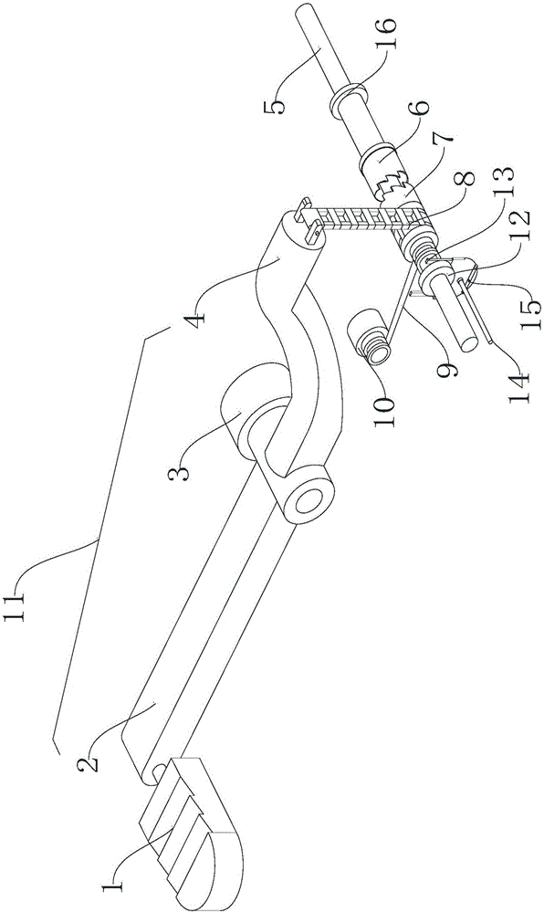
[0023] Embodiment 1: A bicycle gyro transmission structure, including a connecting rod 11, a driven transmission tooth 6, a driving transmission tooth 7, and a transmission belt 8, wherein the connecting rod 11 is connected to the driving transmission tooth 7 through the transmission belt 8, and the driving transmission tooth 7 passes through the recovery The mechanism rotates around the wheel shaft 5 of the bicycle, the driving gear 7 and the driven gear 6 are driven in one direction through the locking teeth and the driven gear 6 is fixed on the hub 16 of the wheel shaft 5 .

Embodiment 2

[0024] Embodiment 2: A bicycle gyro transmission structure, one side of the active transmission tooth 7 is connected with a toggle block 12 with a clearance fit with the wheel shaft 5, one side of the toggle block 12 is provided with a toggle tooth 13, and the toggle tooth 13 The lower part is provided with conversion control line 14, return spring 15. The recovery mechanism includes a steel wire rope 9 and a coil spring 10 , and the coil spring 10 drives the steel wire rope 9 to connect with the driving tooth 7 . The connecting rod 11 includes a front rod body 2 and a rear rod body 4 , both of which are fixedly connected with the hinge 3 . The rest of the structure is the same as that described in Example 1.

Embodiment 3

[0025] Embodiment 3: A kind of bicycle, at least comprises vehicle frame, driving wheel, and driving wheel is installed on the vehicle frame through the axle 5 that has hub 16, and the two sides of described vehicle frame are provided with bicycle gyro transmission structure, and described bicycle gyro The transmission structure includes a connecting rod 11, a driven transmission tooth 6, a driving transmission tooth 7, and a transmission belt 8, wherein the connecting rod 11 is hinged on the vehicle frame, and a pedal 1 is arranged at the head end of the connecting rod 11, and the connecting rod 11 The end is connected with the driving gear 7 through the transmission belt 8, the driving gear 7 rotates around the wheel shaft 5 through the return mechanism, and the driving gear 7 and the driven gear 6 are unidirectionally transmitted through the locking teeth, and the driven gear 6 is fixed on the hub 16 on.


PUM


Abstract

The invention discloses a bicycle gyro transmission structure and a bicycle equipped with the structure, belongs to the field of bicycle, and is used for traveling. The bicycle gyro transmission structure comprises a connecting rod, a wheel axle, a hub, a driven transmission tooth, a driving transmission tooth and a transmission belt, wherein the connecting rod is connected with the driving transmission tooth through the transmission belt; the driving transmission tooth rotates around the wheel axle through a returning mechanism; the driving transmission tooth and the driven transmission tooth perform unidirectional transmission through a clamping tooth; the driven transmission tooth is fixed on the wheel axle. The bicycle provided by the invention is at least equipped with a frame and a driving wheel besides the above structure; the driving wheel is mounted on the frame through the wheel axle and the hub. According to the technical scheme, the bicycle driving wheel can be driven to rotate at high speed by using a novel transmission structure provided by the invention; the bicycle gyro transmission structure can be operated by acting with single foot or both feet at the same time, and is stable and high in transmission efficiency.

Description

technical field [0001] The invention belongs to the field of bicycles, and in particular relates to a bicycle gyro transmission structure for two or more wheels and a bicycle equipped with the structure. Background technique [0002] Traditional bicycles are driven by a crank structure and a chain. When people ride, they often exert force on one foot. Through the action of the pedals, the crank structure rotates to drive the chain to make the driving wheel (usually the rear wheel) rotate, which is time-consuming and labor-intensive. Transmission efficiency is low. If you want to increase the rotation of the drive wheel, you generally need to increase the rotational speed of the crank or increase the gear tooth matching ratio of the crank transmission mechanism. [0003] With the development of social economy, people's demand for green travel is relatively strong. The traditional bicycle structure cannot meet the use needs and aesthetic requirements of the newborn crowd, an...

Claims


Application Information

Patent Timeline
Patent Type & Authority Applications(China)
IPC IPC(8): B62M1/24B62M11/02
CPCB62M1/24B62M11/02
Inventor 李延芝
Owner 李延芝
Why Eureka
Try Eureka