Waste compression device

A technology of garbage compression and garbage, applied in the direction of garbage conveying, garbage collection, storage devices, etc., can solve the problems of reducing the garbage carrying space, small garbage carrying capacity of the box, and low garbage compression efficiency, so as to expand the carrying space and compress the garbage. , the effect of reducing the number of round trips

Active Publication Date: 2017-05-10
XIAMEN YULONG MACHINERY
View PDF15 Cites 0 Cited by
  • Summary
  • Abstract
  • Description
  • Claims
  • Application Information

AI Technical Summary

Problems solved by technology

But this garbage compressor compression device is placed in the whole box, and the oil cylinder will take up a large part of the space of the whole box, reducing the effective garbage carrying space in the whole box, and the stroke of the oil cylinder will be limited, so the compression efficiency of garbage is relatively low. Low, the garbage carrying capacity of the box is small

Method used


Image

  • Waste compression device
  • Waste compression device
  • Waste compression device

Examples


Embodiment 1

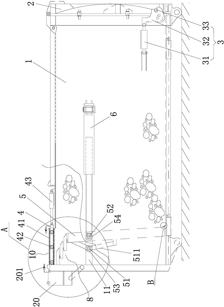
[0032] Embodiment one, Figure 1 to Figure 7 As shown, a garbage compression device includes a box body 1, a rear door 2 is hinged at the rear of the box body 1, and a locking mechanism 3 is provided between the box body 1 and the back door 2, and the locking mechanism 3 includes a locking oil cylinder 31. The hook arm 32 and the hanging pin 33, the middle part of the hook arm 32 is hinged at the lower part of the rear side of the box body 1, the hanging pin 33 is fixed at the lower part of the side of the rear door 2, and one end of the locking cylinder 31 is hinged with one end of the hook arm 32 , the other end of the locking oil cylinder 31 is hinged on the side of the box body 1 , and the other end of the hook arm 32 is provided with a hook groove to cooperate with the hanger pin 33 .

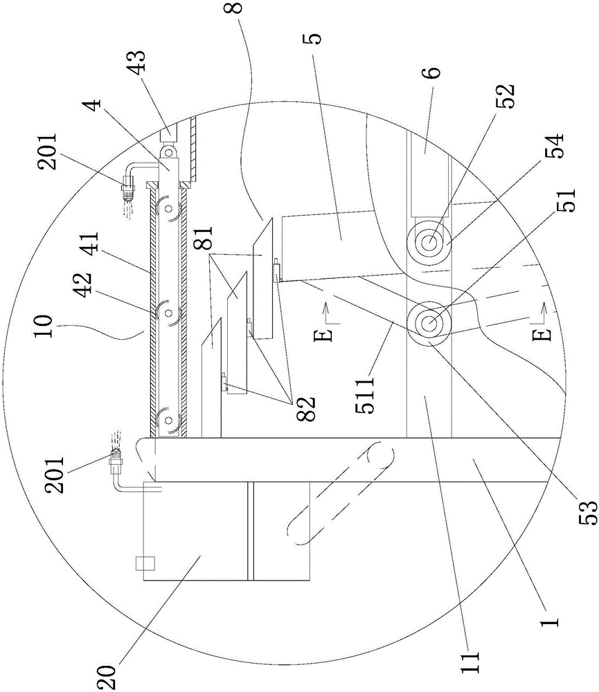
[0033]The front side of the box body 1 top is provided with a garbage feeding port 10, and the garbage feeding port 10 is provided with an openable top cover 4, a push plate 5 is housed in...

Embodiment 2

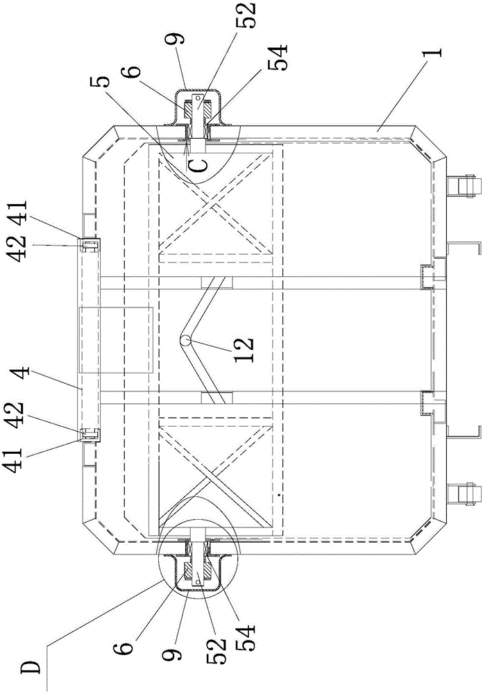
[0045] Embodiment two, Figure 12 As shown, it differs from Embodiment 1 in that when two push-pull oil cylinders 6 are installed on the two outer sides of the box body 1, two push-pull oil cylinders 6 are provided on the two outer sides of the box body 1 corresponding to the two push-pull oil cylinders 6. The elongated transverse through hole 11, two second connecting pins 52 are fixedly connected to both sides of the push plate 5, and each second connecting pin 52 passes through an elongated transverse through hole 11 and one end of a push-pull oil cylinder 6 Hinged, the other end of each push-pull cylinder 6 is hinged on the outer surface of the box body 1, the middle part of each second connecting pin 52 is covered with a second roller 54, and the second roller 54 moves along the inner wall of the long strip-shaped transverse through hole 11 . At this time, both sides of the push plate 5 do not need to be fixedly connected to the first connecting pin 52 as described in th...


PUM


Abstract

The invention discloses a waste compression device which comprises a box body; a waste feed port is formed in the front side of the top of the box body; a push board is arranged in the box body; one push-pull oil cylinder or two push-pull oil cylinders is or are arranged on each of the two outer sides of the box body; strip-shaped transverse through holes are formed in parts of the two side surfaces, corresponding to the push-pull oil cylinders, of the box body; when one push-pull oil cylinder is arranged on each of the two sides of the box body, a first connecting pin and a second connecting pin are fixedly connected with each of the two sides of the push board, a first roller is arranged on one first connecting pin and moves along the internal wall of one strip-shaped transverse through hole correspondingly, and one second connecting pin penetrates through one strip-shaped transverse through hole and is hinged to one end of one push-pull oil cylinder correspondingly; when two push-pull oil cylinders are arranged on each of the two sides of the box body, two second connecting pins are fixedly connected with each of the two sides of the push board, each second connecting pin penetrates through one strip-shaped transverse through hole and is hinged to one end of one push-pull oil cylinder correspondingly, at least one second connecting pin is provided with a second roller at the middle part of the second connecting pin in a sleeving manner, and the second rollers move along the internal walls of the strip-shaped transverse through holes correspondingly. Effective waste bearing space in the box body of the waste compression device is large, the compression efficiency is high, and the waste collection quantity of the box body is high.

Description

technical field [0001] The invention relates to garbage compression equipment, in particular to a garbage compression device. Background technique [0002] Nowadays, in order to improve the efficiency of garbage transfer, the garbage in most cities needs to be compressed by compression equipment before being transferred. At present, the compression equipment is usually installed in the garbage transfer station to work. It is very difficult to build a new garbage transfer station in a residential area because the garbage transfer station will produce problems such as odor and garbage seepage, which will cause secondary pollution to the environment. Therefore, in the process of garbage disposal, some mobile garbage collection and compression equipment are needed to form a garbage direct transportation system to reduce secondary pollution to the environment. At present, in the technical field of garbage compression equipment, some mobile garbage compression equipment have bee...

Claims


Application Information

Patent Timeline
IPC IPC(8): B65F9/00
CPCB65F9/00Y02W30/10
Inventor 李振营陈卿雁廖德峰
Owner XIAMEN YULONG MACHINERY
Why Eureka
Try Eureka