Vertical lifting conveyor

A vertical lifting and conveyor technology, applied in the direction of conveyor, conveyor objects, transportation and packaging, etc., can solve the problem that the belt of the hoist is easy to deviate, the replacement of wearing parts of the belt is troublesome, and the lifting block is easy to be degummed and loosened, etc. problem, to achieve the effect of not easy to deviate, low cost and beautiful appearance

Inactive Publication Date: 2017-05-10
新火炬科技有限公司
View PDF8 Cites 2 Cited by
  • Summary
  • Abstract
  • Description
  • Claims
  • Application Information

AI Technical Summary

Problems solved by technology

[0003] The above types are common forms of conveying from low to high in industrial automation. In industrial production, some of them use vertical lifting, most of which are placed vertically by belt conveyors, and then glued to the belt. The main disadvantage of this method is that the stuck lifting block is easy to be degummed and loose after long-term use, and the locked lifting block is prone to interference with the motor drive shaft and driven shaft, wear or loosen. This type of hoist is mainly because the lifting block is not durable, easy to damage, and needs to be replaced frequently
In addition, the belt of this type of hoist is easy to run off, which is more likely to cause damage to the hoist. At the same time, it is very troublesome to replace the wearing parts of the belt of this type of vertical hoist. It is necessary to disassemble the driving shaft and driven shaft to complete the replacement, which is troublesome to maintain. high maintenance cost
[0004] Based on the use and current situation of the above-mentioned various hoists, no vertical hoist has been found that can not only achieve the vertical lifting effect at low cost, but also be durable, beautiful in appearance, not easy to deviate from the conveyor belt, and simple and efficient in maintenance. Conveyor

Method used


Image

  • Vertical lifting conveyor
  • Vertical lifting conveyor
  • Vertical lifting conveyor

Examples


Embodiment Construction

[0024] The technical solution of the present invention will be further described below in conjunction with the accompanying drawings.

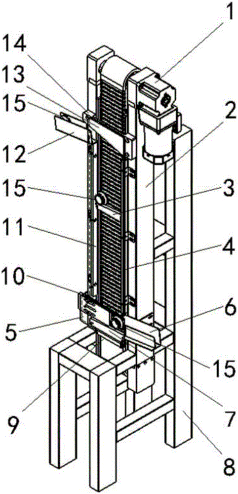
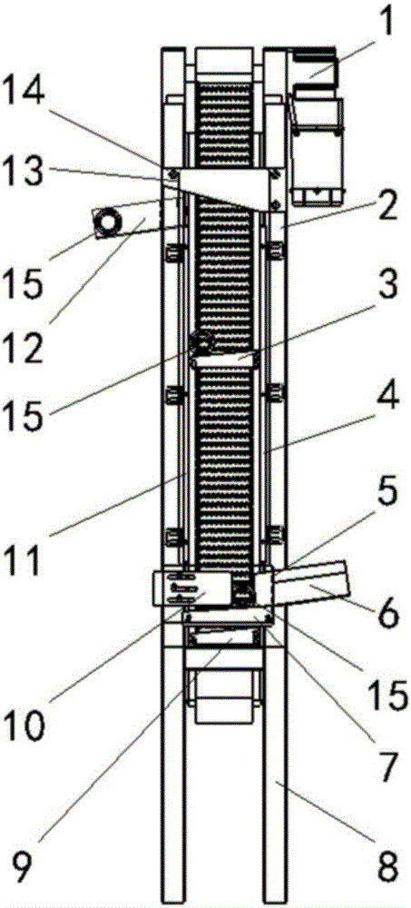
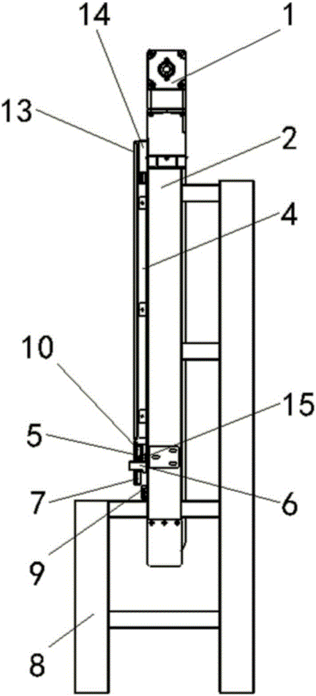
[0025] Such as Figure 1 to Figure 4 As shown, the vertical lifting conveyor of the present invention includes a motor 1, a chain plate conveyor unit 2, a lifting block unit 2 3, a right baffle plate 4, an outer baffle plate 5 for feeding suspension, and a feeding channel 6, and a lower feeding suspension Support plate 7, bracket unit 8, lifting block unit 1 9, feeding suspension adjustment plate 10, left baffle plate 11, discharge channel 12, lifting outer baffle plate 13, lifting blocking plate 14, lifting block 16, upper connecting circular shaft 17, the right mounting block 18, the following connecting circular shaft 19, the lower chain plate joint 20, the left mounting block 21, and the upper chain plate joint 22. The workpiece 15 is not a component of the present invention, but only a symbol for description. For clear and simple expres...


PUM


Abstract

The invention relates to the field of workpiece hoist and transportation on automatic production connection lines, in particular to a vertical lifting conveyor. A link plate conveying unit disclosed by the invention is in closed connection formed by connecting a plurality of lower link plates and a plurality of upper link plates in an end to end manner. A left baffle and a right baffle are arranged on two sides of the front side of the link plate conveying unit; an outer lifting baffle is arranged in a front side area of a to-be-lifted section of the link plate conveying unit; a lifting barrier plate is arranged on the upper part of a space between the outer lifting baffle and the link plate conveying unit; a discharging channel is formed in one side below the lifting barrier plate; a plurality of groups of lifting block units are mounted on the link plate conveying unit; a feeding channel is mounted on one side on the lower part of the link plate conveying unit. The device disclosed by the invention is capable of realizing vertical lifting of workpieces and low in cost, and has the advantages that the device is durable in use and attractive in appearance, the lifting block units are easy to mount, the distance is easy to adjust, parts on a link plate conveyor belt are easy to replace and maintain.

Description

technical field [0001] The invention relates to the field of automatic production line workpiece lifting and conveying, in particular to a vertical lifting conveyor. Background technique [0002] At present, in automated production, there are often products that are transferred from a low place to a high place. The current common practice is generally divided into the following methods: some use industrial robots to move from low to high places; some use cylinders or hydraulic cylinders to pass through After controlling the solenoid valve, the transfer from low to high is realized; one part adopts slope conveying and lifting conveyor belt to climb and convey from low to high, one part uses motor to drive the screw pair to complete the conveying from low to high, and one part uses motor to drive the chain It is conveyed upwards, and part of it is conveyed upwards by a spiral rotating chain belt. [0003] The above types are common forms of conveying from low to high in indus...

Claims


Application Information

Patent Timeline
Patent Type & Authority Applications(China)
IPC IPC(8): B65G17/06B65G17/48B65G17/38B65G47/88B65G47/04
CPCB65G17/065B65G17/38B65G17/48B65G47/04B65G47/883
Inventor 张伟
Owner 新火炬科技有限公司
Why Eureka
Try Eureka