
Single-wheel deflection optical fibre twisting equipment

A yaw, optical fiber technology, applied in glass manufacturing equipment, manufacturing tools, glass production and other directions, can solve the problems of complex transmission chain of the yaw mechanism, difficult assembly and debugging, complex structure, etc., to achieve simple and convenient debugging and continuous transmission. Stable and reliable, the effect of avoiding fiber swing

Active Publication Date: 2017-05-10
SHANGHAI YUPIN COMM TECH
View PDF5 Cites 2 Cited by
  • Summary
  • Abstract
  • Description
  • Claims
  • Application Information

AI Technical Summary

Problems solved by technology

Moreover, the transmission chain of the yaw mechanism is relatively complicated, and it is difficult to assemble and debug
At the same time, due to the complex structure and the use of a large number of expensive components, the cost of the entire product is relatively high

Method used


Image

  • Single-wheel deflection optical fibre twisting equipment
  • Single-wheel deflection optical fibre twisting equipment
  • Single-wheel deflection optical fibre twisting equipment

Examples


Embodiment 1

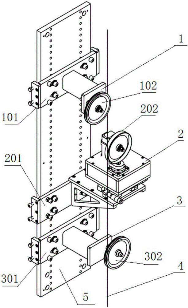
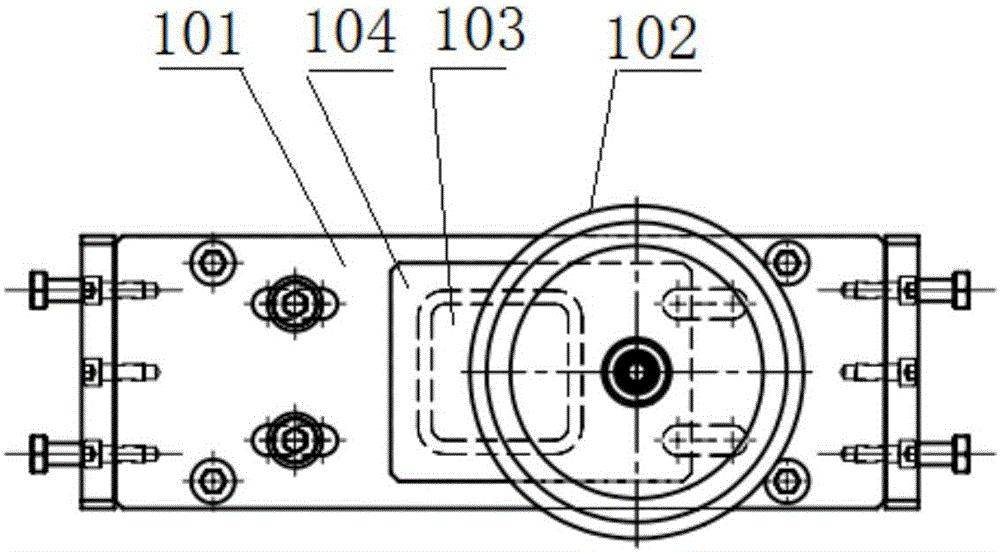
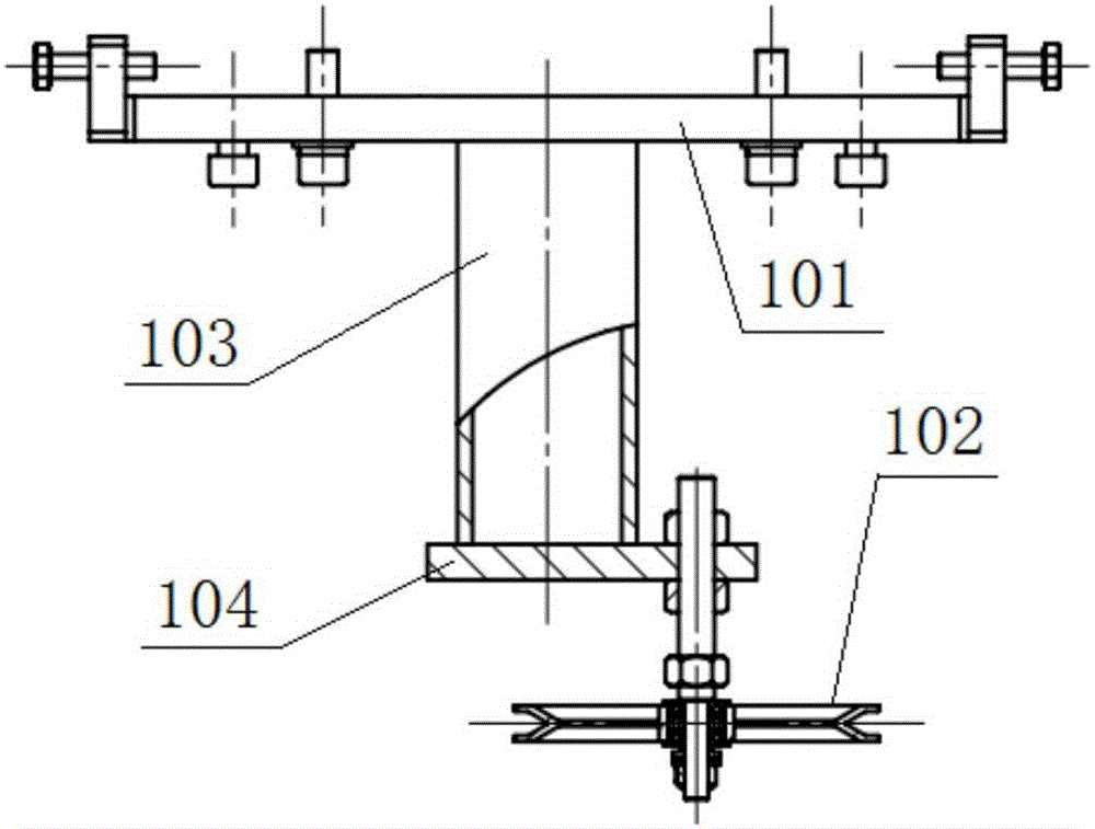
[0023] Embodiment 1: as attached figure 1 As shown, the frame 5 is erected and fixed, and the upper positioning wheel set 1, the single wheel yaw mechanism 2 and the lower positioning wheel set 3 are installed sequentially on the frame 5 from top to bottom, wherein, the rear portion of the upper positioning wheel set 1 passes through the upper The positioning seat 101 is installed on the frame 5, and the upper positioning guide wheel 102 is installed on the front side of the upper positioning seat 101. The yaw wheel 202 is installed on the side, the rear part of the lower positioning wheel group 3 is installed on the frame 5 through the lower positioning seat 301, the lower positioning guide wheel 302 is installed on the front side of the lower positioning seat 301, the upper positioning guide wheel 102 and the lower positioning guide wheel 302 There are respectively guide wheel grooves on the outer edge of the yaw wheel 202, and the optical fiber 4 is vertically embedded in e...


PUM


Abstract

The invention discloses single-wheel deflection optical fibre twisting equipment. An upper positioning wheel set (1), a single wheel deflection mechanism (2) and a lower positioning wheel set (3) are mounted on a machine frame (5) in sequence from top to bottom; through centering adjustment of the upper positioning wheel set (1) and the lower positioning wheel set (3), two guide wheel grooves of an upper positioning guide wheel (102) and a lower positioning guide wheel (302) are simultaneously tangent to the surface of an optical fibre (4); optical fibre twisting movement is transferred upwards stably; the continuity of periodic deflection movement is realized by the single wheel deflection mechanism (2) adopting a continuous transmission mechanism; by adopting a single-wheel periodic deflection structure, the two side surfaces of a V-shaped wheel groove are in contact with the optical fibre alternately, so that periodic reciprocating twisting of the optical fibre is realized; a motor of the transmission mechanism operates continuously in a single direction, so that forward and backward reciprocating movement is not required. The positioning guide wheels are added above and below the deflection wheel so as to ensure that the optical fibre is only twisted, and the swinging of the optical fibre is avoided. The equipment is easy, quick and convenient to machine, assemble and debug; the manufacturing and maintenance cost is remarkably reduced; technical requirements on an optical fibre drawing process can be met practically and effectively.

Description

technical field [0001] The invention relates to the technology of reducing optical fiber polarization mode dispersion PMD in the optical fiber manufacturing process, which belongs to the manufacturing and molding process of C03B glass, mineral or slag wool in the IPC classification, especially the structure improvement technology of optical fiber twisting equipment in the communication optical fiber drawing production line, especially It is a single-wheel deflection fiber twisting device. Background technique [0002] In the drawing process of optical fiber manufacturing technology, twisting is an effective means to reduce the PMD of optical fiber polarization mode dispersion. By rubbing the fiber in the forward and reverse directions, the fiber at the position above the softening temperature is periodically twisted in the forward and reverse directions, so that the fiber can maintain a certain number of twists per unit length after cooling, reducing the birefringence or In...

Claims


Application Information

Patent Timeline
Patent Type & Authority Applications(China)
IPC IPC(8): C03B37/03
CPCC03B37/03Y02P40/57
Inventor 丁斌仁义龙陈兵
Owner SHANGHAI YUPIN COMM TECH
Learn More