Method of calibrating clutch actuator

A clutch actuator and sensor technology, applied in clutches, couplings, control devices, etc., can solve problems such as inaccuracy, time-consuming estimation, and large additional costs.

Active Publication Date: 2017-12-05
ROBERT BOSCH GMBH
View PDF14 Cites 0 Cited by
  • Summary
  • Abstract
  • Description
  • Claims
  • Application Information

AI Technical Summary

Problems solved by technology

However, it has been shown that model-based estimation is laborious and ina

Method used


Image

  • Method of calibrating clutch actuator
  • Method of calibrating clutch actuator

Examples


Embodiment Construction

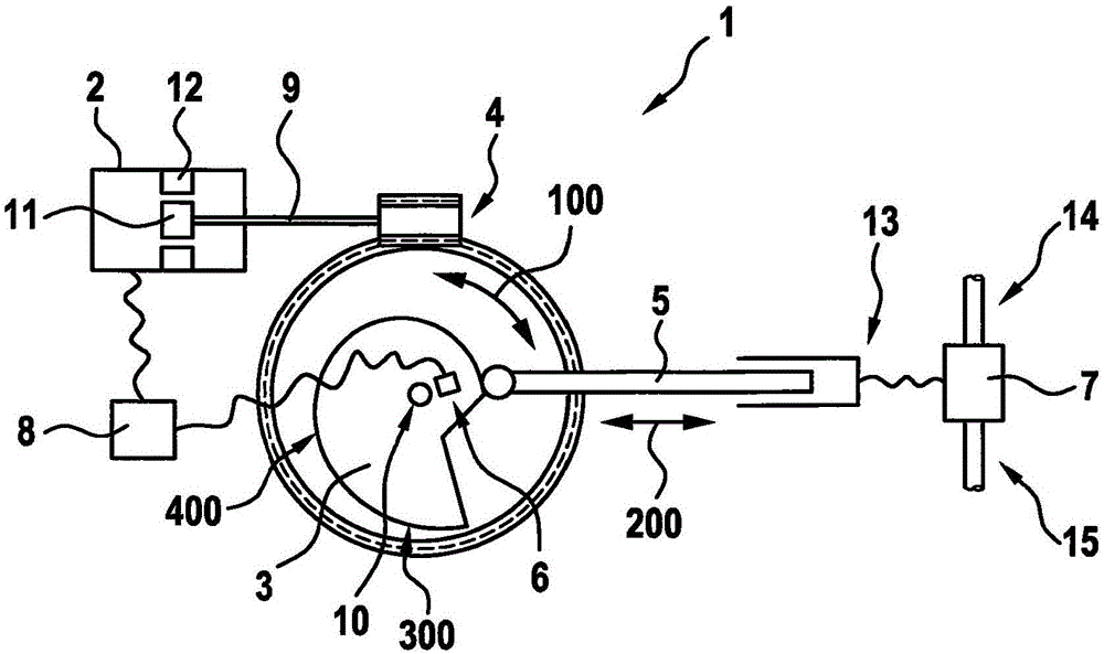
[0025] figure 1 A clutch actuator 1 according to an embodiment of the invention is shown. The clutch actuator 1 is used to actuate the clutch 7 . For this purpose, the actuator 5 of the clutch actuator 1 executes a translational movement 200 . The translational movement 200 can be transmitted to the clutch 7 via the hydraulic system 13, whereby the clutch 7 can be engaged and disengaged. The clutch 7 serves to separate or connect the input shaft 14 and the output shaft 15, wherein the input shaft 14 can preferably be connected to the drive motor and the output shaft 15 can preferably be connected to the output device. A further force transmission element different from the hydraulic system 13 can advantageously be present between the actuator 5 and the clutch 7 .

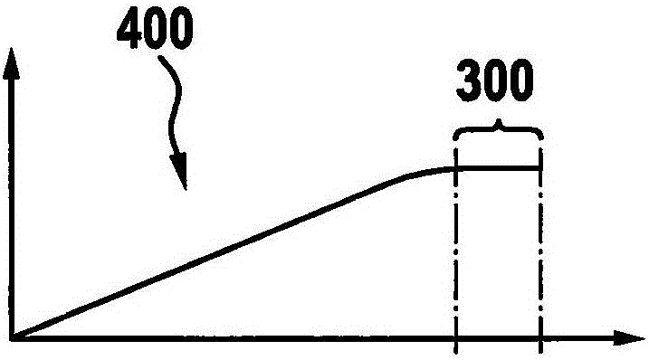
[0026] In order to generate the translational movement 200 of the actuator 5, a cam disk 3 is present. The cam disc 3 has a pivot point 10 about which the cam disc 3 can rotate. The rotational movement of the c...


PUM


Abstract

The present invention relates to a method for calibrating a clutch actuator. The clutch actuator comprises a servomotor, a cam w, an adjusting element, and a sensor. The clutch actuator is characterized by comprising the following steps that first operation of the servomotor is conducted by a first stator space vector, so the cam can rotate in a first direction, and a first data group composed of the first position of the first space vector and the first actual position of the cam can be determined; second operation of the servomotor is conducted by a second space stator vector, so the cam can rotate in a second direction opposite to the first direction and a second data group composed of the second space vector position and the a second practical direction of the cam disc is determined. The clutch actuator is calibrated with the determined first and second data groups; by rotation of the cam via the first and second operation, the executing element can be applied against a bration zone of a constant radius of the cam disc; and the space vector represents the magneticfield of the stator.

Description

technical field [0001] The present invention relates to a method for calibrating a clutch actuator. Furthermore, the invention relates to a clutch actuator in which calibration is simplified. Background technique [0002] Clutch actuators are known from the prior art. Such a clutch actuator can, for example, comprise a permanently excited synchronous machine, such as a brushless DC motor used as the actuator drive. Such brushless DC motors must be electronically commutated, for which a real-time angular position of the permanently excited rotor is required. This is often achieved by means of sensors for detecting torsion of the motor shaft. Alternatively, the sensor can be mounted on an actuator driven by a brushless DC motor. In this case, the brushless DC motor must undergo basic adaptation before operation. This includes establishing a link between the measured sensor value and the mechanical angle of the motor shaft. Furthermore, the linearization error of the roto...

Claims


Application Information

Patent Timeline
IPC IPC(8): F16D48/06
CPCF16D48/06F16D2300/18F16D2500/1024F16D2500/302F16D2500/5018F16D2500/70205B60K23/02F16D2500/3021F16D2500/3026F16D2500/3067F16D2500/50245
Inventor T·克洛伊贝尔U·西贝尔
Owner ROBERT BOSCH GMBH
Why Eureka
Try Eureka