A textile machine faucet frame

A textile machine and faucet technology, applied in the direction of looms, textiles, textiles and papermaking, etc., can solve the problems of fabric pollution, scratches on people and objects, sharp corners of channel steel, etc., to improve stability and life, and prevent foreign matter Entry, pollution prevention effect

Active Publication Date: 2019-05-03
WUJIANG RICHUN TEXTILE MACHINERY
View PDF6 Cites 1 Cited by
  • Summary
  • Abstract
  • Description
  • Claims
  • Application Information

AI Technical Summary

Problems solved by technology

Since the two channel steels are independently fixed and connected to the left bracket and the right bracket bracket, the overall stability of the frame is not high, and the individual channel steels are relatively thin, and the vibration of the textile machine is relatively strong when the textile machine is working; The gap of the steel bracket is large, resulting in a large exposed area of ​​the equipment and insufficient protection, which may easily cause the lubricating oil inside the machine to drip onto the fabric, causing pollution to the fabric; and the corners of the channel steel are sharp, which is easy to cause damage to personnel and objects. scratch

Method used


Image

  • A textile machine faucet frame
  • A textile machine faucet frame
  • A textile machine faucet frame

Examples


Embodiment Construction

[0025] The preferred embodiments of the present invention will be described in detail below with reference to the accompanying drawings.

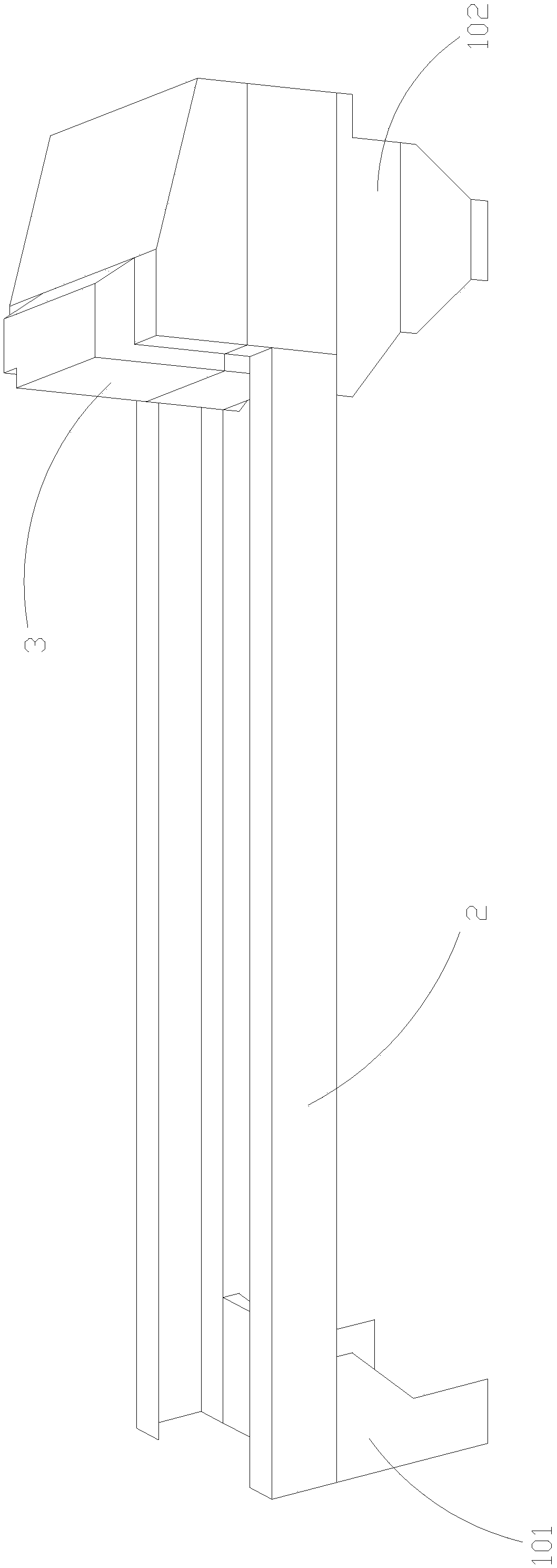
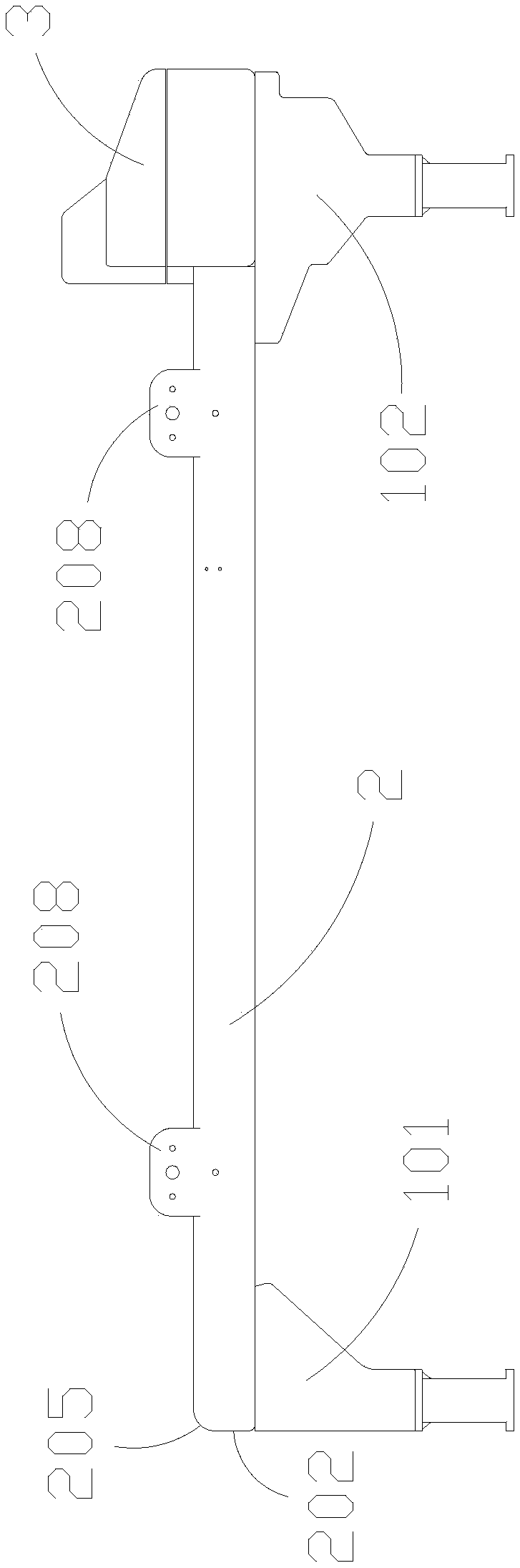
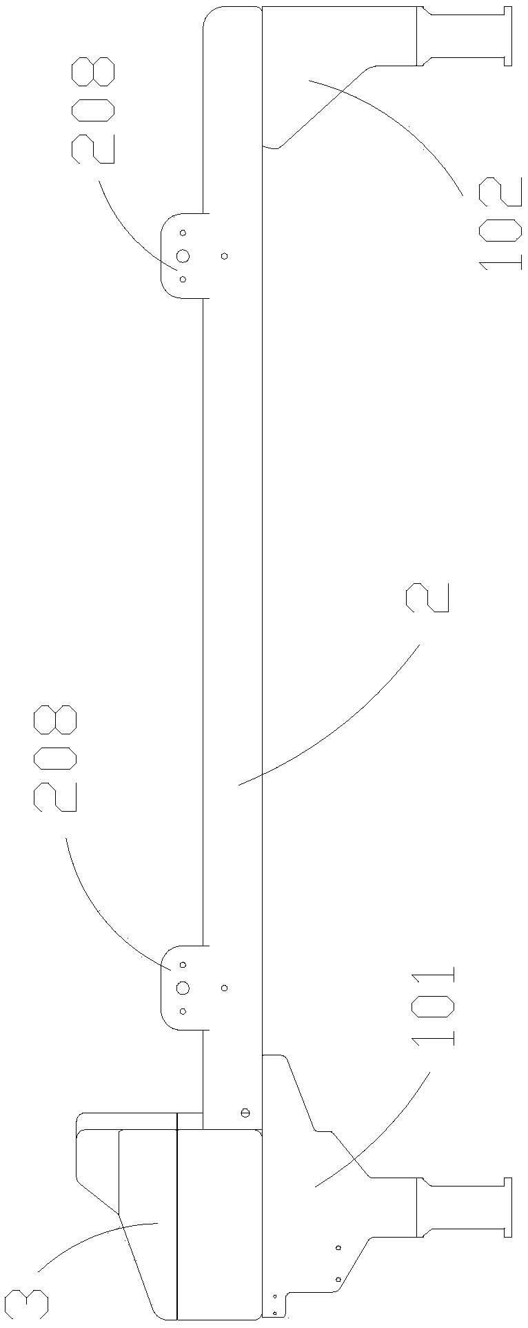
[0026] see Figure 2-7 , A textile machine faucet frame of the present invention includes a left bracket 101 , a right bracket 102 , a beam 2 and a transmission mechanism 3 .

[0027] The cross beam 2 is a metal bending beam, the first end of the metal bending beam is fixed on one of the left bracket 101 and the right bracket 102 in parallel with the transmission mechanism 3, and the second end of the metal bending beam is along the distance away from the transmission mechanism. The direction extension is fixed on the other of the left bracket 101 and the right bracket 102 . In this embodiment, the right end of the metal bending beam is preferably fixed on the right bracket 102 in parallel with the transmission mechanism 3 , and the other end of the metal bending beam is extended and fixed on the left bracket 101 along the direction away f...


PUM


Abstract

The invention provides a textile machine head rack which comprises a left-side support, a right-side support and a cross beam. The cross beam is a metal bent beam, wherein the metal bent beam comprises a base plate arranged on the left-side support and the right-side support in a bilaterally extending and striding mode, at least one end of the left end and the right end of the base plate is upwards bent to form an end cover plate, and the front side and the rear side of the base plate are respectively and upward bent to form a front side plate and a rear side plate. The whole textile machine head rack is formed by folding a metal plate and is stable in structure. The rack is tight in protection, can effectively prevent foreign matter from entering a machine to cause damage, can also prevent lubricating oil inside the machine from dropping onto a fabric to pollute the fabric. Round-angle transition is adopted for corners of the rack, and the phenomenon that sharp corners hurt persons or damage articles is avoided.

Description

technical field [0001] The invention relates to the technical field of textile machines, in particular to a faucet frame of a textile machine. Background technique [0002] Refer to the attached figure 1 , the faucet frame of the textile machine includes a left bracket 101, a right bracket 102 and a beam 2 spanning between the left bracket and the right bracket. The traditional beam adopts two channel steels arranged side by side at intervals, that is, the two channel steels are arranged in parallel, and the openings are relatively fixed between the left bracket and the right bracket respectively to support other parts of the textile machine. Since the two channel steels are independently fixed and connected to the left bracket and the right bracket bracket, the overall stability of the frame is not high, and the individual channel steels are relatively thin, and the textile machine shakes strongly when working; the two channels The gap of the steel bracket is large, resul...

Claims


Application Information

Patent Timeline
Patent Type & Authority Patents(China)
IPC IPC(8): D03D49/02
CPCD03D49/02
Inventor 侯景奎
Owner WUJIANG RICHUN TEXTILE MACHINERY
Why Eureka
Try Eureka