
Track lifting and lining device equipped with detection vehicle

A technology for detecting trolleys and driving lanes, applied in the directions of roads, tracks, ballast layers, etc., can solve problems such as complex structure design of working trolleys

Inactive Publication Date: 2017-05-10
肖玉清 +2
View PDF2 Cites 0 Cited by
  • Summary
  • Abstract
  • Description
  • Claims
  • Application Information

AI Technical Summary

Problems solved by technology

[0003] The tamping device of the DC-32 tamping car, and the C-point detection trolley (in the first section of Chapter 8 of the book "Tamping Vehicle for Leveling and Raising Tracks", "point C" refers specifically to the tamping device and the starting point The detection trolley between the track-setting devices) and the track-setting device are installed on the frame relatively independently from the back to the front. The DCL-32 tamping car also installs these three devices on the frame relatively independently from the back to the front. On the frame of the working trolley, the structural design of the working trolley frame is very complicated

Method used


Image

  • Track lifting and lining device equipped with detection vehicle
  • Track lifting and lining device equipped with detection vehicle
  • Track lifting and lining device equipped with detection vehicle

Examples


Embodiment Construction

[0015] The specific embodiment is described below with reference to the accompanying drawings;

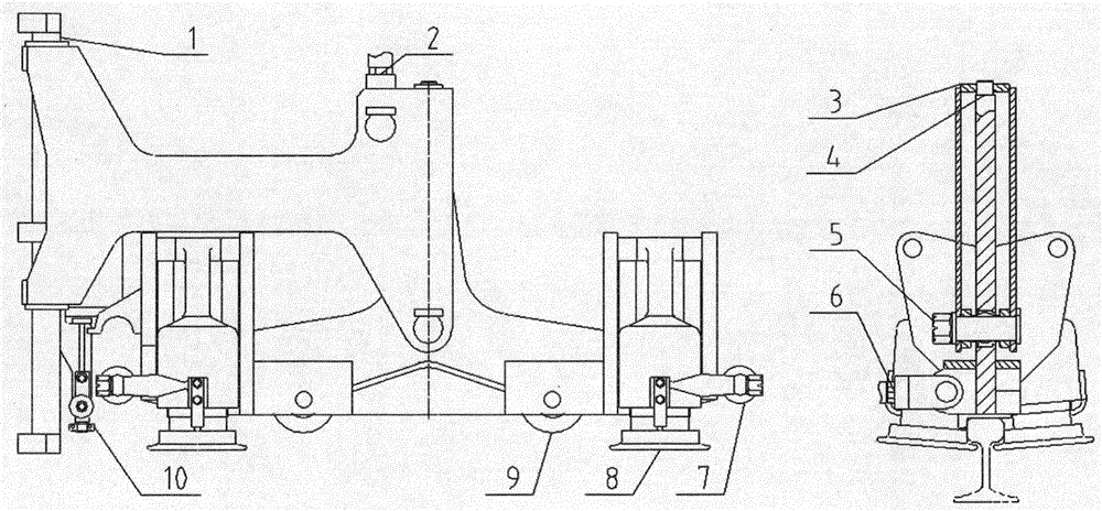
[0016] figure 1 It is a general diagram of the lifting track device equipped with a detection trolley. The left figure is a front view of the guide column (1) adjacent to the C point detection trolley (10), and the swing hanger (3) is in the hanging and locked position. The figure on the right is a sectional view of the assembly relationship at the center line of symmetry of the clamp bracket (4).

[0017] The guide column (1) shown in the left figure can move upward relative to the swing hanger (3), and the lower structure does not interfere with the C-point detection trolley (10). After the guide post (1) is installed on the frame reference plane, the swing hanger (3) can swing or move up and down relative to the guide post (1).

[0018] As shown in the figure on the right, the cylindrical shaft section at the upper end of the clamp bracket (4) is inserted into the shaft seat h...


PUM


Abstract

The invention relates to a track lifting and lining device equipped with a detection vehicle, and the technical basis thereof is a track lifting-lining device used for 08-32 stepping double railroad tie tamping machines (for details, see the third section of the third chapter in a railroad employee on-the-post training nation-compiled textbook Leveling-Lifting-Lining-Tamping Machine published by China Railway Publishing House with an ISBN of 7-113-02542-0) provided by PLASSER & THEURER company (hereinafter referred to as P&T company) of Austria. The main point of the invention is to rectify and reform the problems known in the prior design. The track lifting and lining device disclosed by the invention is equipped with a C-point detection vehicle which can be mounted on the track lifting and lining device. While being used to develop a novel continuous tamping machine, the track lifting and lining device can facilitate to simplify the design of the frame structure of a working vehicle.

Description

technical field [0001] The invention relates to a track lifting device equipped with a detection trolley. The technical basis is the track lifting device for the 08-32 step-type double-pillow tamping vehicle of the Austrian PLASSER&THEURER company (hereinafter referred to as P&T company) (see China for details). Railway Publishing House ISBN 7-113-02542-0 Railway Workers Post Training System Compiled Textbook "Copy Leveling Up and Dial Track Tamping Car" book third chapter third section), the invention point is to rectify the problems existing in the original design , equipped with a C-point detection trolley that can be installed on the lifting device. When the track lifting device is used in the research and development of a new type of continuous tamping vehicle, it can provide convenient conditions for simplifying the design of the frame structure of the working trolley. Background technique [0002] The Ministry of Railways of China introduced P&T's 08-32 stepping doub...

Claims


Application Information

Patent Timeline
Patent Type & Authority Applications(China)
IPC IPC(8): E01B27/17E01B35/00
CPCE01B27/17E01B35/00
Inventor 肖玉清邢崇华肖劲翔
Owner 肖玉清
Learn More