Integrated pylon structure for propulsion system

Active Publication Date: 2015-05-07
COMAC +1
View PDF2 Cites 10 Cited by
  • Summary
  • Abstract
  • Description
  • Claims
  • Application Information

AI Technical Summary

Benefits of technology

[0036]Advantageous effects of the present invention are as follow: the engine thrust reverser cowl is directly connected to the sidewall of the pylon box segment, and the thrust reverser cowl is guided to open via the

Problems solved by technology

Besides, the front installation joint 20′ is an individual component independent from th

Method used


Image

  • Integrated pylon structure for propulsion system
  • Integrated pylon structure for propulsion system
  • Integrated pylon structure for propulsion system

Examples


Example

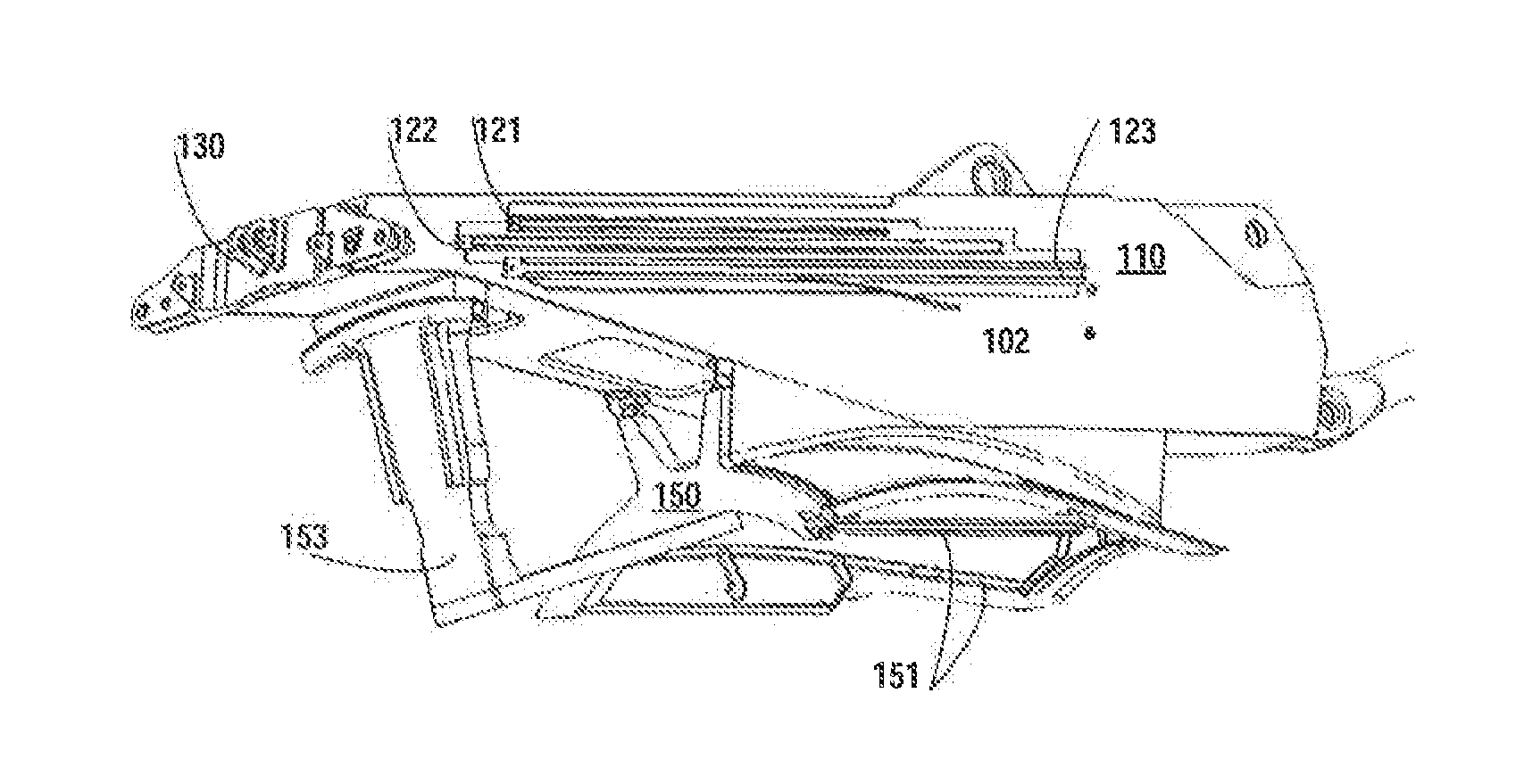
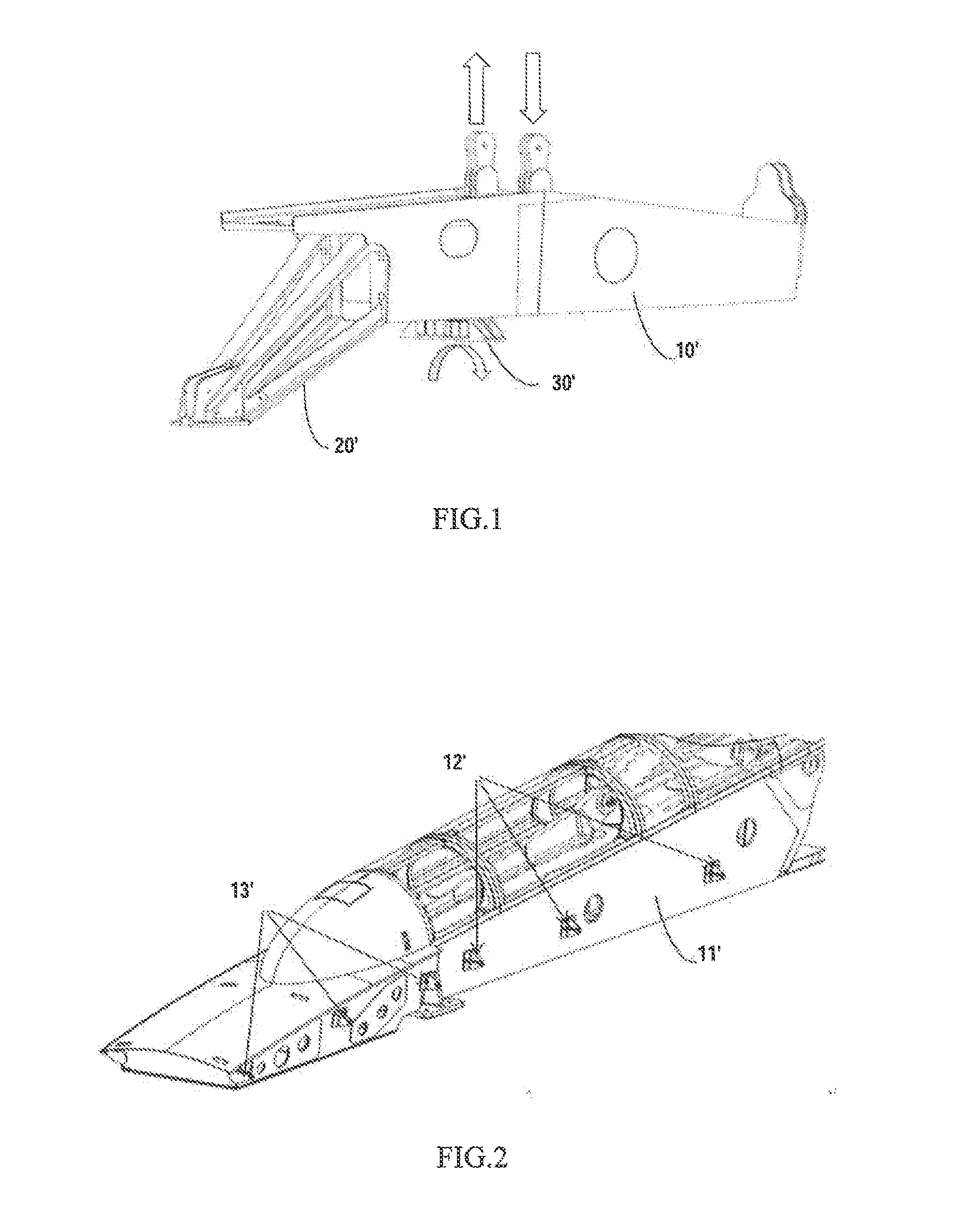
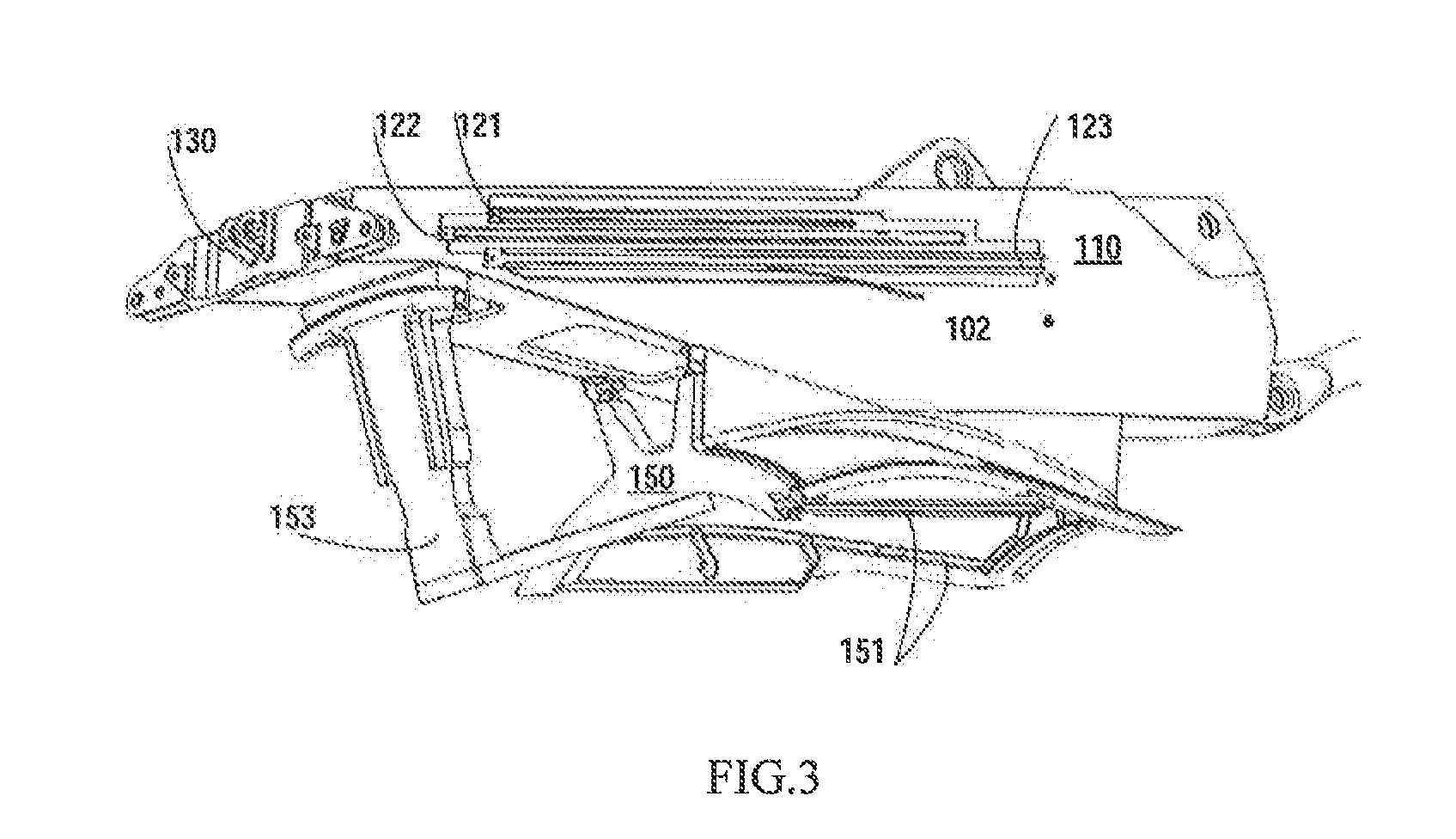
[0054]Embodiments are described in detail below with reference to figures which constitute part of the description. The figures exemplarily exhibit specific embodiments, and the present invention is implemented in these embodiments. The shown embodiments are not intended to exhaust all embodiments according to the present invention. It may be appreciated that other embodiments may be used, and structural or logical changes can be made without departing from the scope of the present invention. Regarding figures, terms indicative of directions such as “outward” and “downward” are used with reference to orientations of the described figures. If the orientations of the figures change, these terms also change accordingly. Since assemblies of the embodiments of the present invention can be implemented in many orientations, these direction terms are used for illustration purpose not for limitation purpose. Hence, the following specific embodiments are not intended to limit the present inve...


PUM


Abstract

An integrated pylon structure for a propulsion system is suitable for one end to be connected to an aircraft wing and the other end to be connected to an aircraft engine. The pylon structure includes a pylon box section (110) formed from an upper and a lower bean, a frame (100) and a side wall panel. The pylon structure has a thrust reverser hood connection structure, provided on the side wall and connected with a nacelle thrust reverser hood having a front fixed hood (301) and a rear movable hood (302). A guide rail allows the rear movable hood to slide and open relative to the pylon box section. The engine thrust reverser hood is directly connected to the side wall of the pylon box section and a guide rail on the side wall guides the opening of the thrust reverser hood.

Description

FIELD OF THE INVENTION[0001]The present invention generally relates to the technical field of structural design, general design, aerodynamic design and strength design of civil aircrafts, and more specifically to a structural connection form of a pylon with an airfoil and an engine.BACKGROUND OF THE INVENTION[0002]A pylon is a connection interface of an aero-engine and an airfoil and mainly functions to mount the engine, transfer engine load, provide a pathway for systems such as a wiring system, environment control system, electrical system and hydraulic system between the engine and the airfoil, and ensure a smooth aerodynamic shape. The design of the pylon structure should take into account various factors such as noise, weight, fuel consumption rate, aerodynamics, system deployment, and engine installation and maintenance.[0003]As shown in FIG. 1, a pylon 10′ in a conventional configuration is usually designed as a rigid box-shaped structure consisting of an upper beam, a lower ...

Claims


Application Information

Patent Timeline
IPC IPC(8): B64D27/26B64D29/06
CPCB64D27/26B64D2027/264B64D29/06B64D27/18F02K1/72Y02T50/40Y02T50/60
Inventor WU, GUANGHUIHAN, KECENZHOU, LIANGDAOYU, QIFENGLIN, GUOZHENGZHANG, HONGJIEZHANG, SHIBIAOWENG, HAOJIEGUO, HAISHAZHANG, PENGFEILI, XIAONANMA, SHIWEIHU, YINYINPENG, SENTANG, HONGGANGYAN, MINGPENG
Owner COMAC
Why Eureka
Try Eureka