
A multi-working condition movable traveling rail support device and its application method

A technology of supporting devices and running rails, which is applied in the direction of track, track laying, track maintenance, etc., can solve the problems of increased workload, limited use range, pinch plate, bolt loss, etc., so as to reduce workload, improve installation and disassembly efficiency, Avoid Lost Effects

Active Publication Date: 2019-12-27
(SUZHOU) RAIL TRANSIT SCI & TECH RES INST CO LTD SHANGHAI CIVIL ENG GRP OF CREC +2
View PDF8 Cites 0 Cited by
  • Summary
  • Abstract
  • Description
  • Claims
  • Application Information

AI Technical Summary

Problems solved by technology

This design has great limitations in use. First, the base of the fixed support device can only be installed on a base with a specific inclination angle, which limits its scope of use, or requires supports of various specifications. The device can meet the construction needs. my country's patent application number: CN201320266036.5 discloses a circular tunnel track-laying machine profile rail support. Although it can be adapted to circular tunnel installation, it cannot be suitable for non-circular bases, and its applicability is still insufficient. Secondly, the fixed-length outriggers lead to the unevenness of the laid track, which is not conducive to the running of the track-laying equipment; in addition, such as my country's patent application number: CN201310277649.3 discloses an adjustable buttress for supporting the track of the tunnel track-laying door crane , the pier can be adjusted according to the angle of the tunnel wall to maintain a vertical state. The running rail is fixed on the pier by using pinch plates and pinch plate bolts. This method of fixing the rails by using pinch plates requires frequent disassembly and assembly of the pinch plates, which increases the workload, and it is easy to cause loss of gussets and bolts

Method used


Image

  • A multi-working condition movable traveling rail support device and its application method
  • A multi-working condition movable traveling rail support device and its application method
  • A multi-working condition movable traveling rail support device and its application method

Examples


Embodiment 1

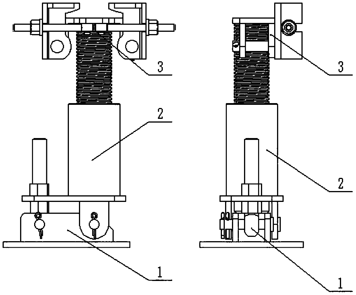
[0032] see figure 1 , the present invention is mainly made up of base 1, supporting leg 2 and bearing rail groove 3 three major parts.

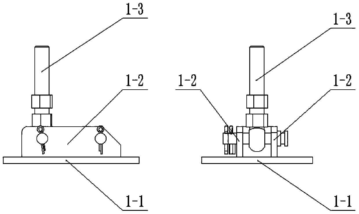
[0033] see figure 2 , Base 1 is made up of base plate 1-1, vertical plate 1-2 and first swing bolt 1-3. The base plate 1-1 is a shaped steel plate, and mounting holes are provided at the four corners for mounting and fixing on the base. The two vertical plates 1-2 are shaped steel plates, which are respectively welded on both sides of the base plate 1-1, and a pin hole is provided at the front and rear respectively, and the first joint bolt 1-3 passes through the pin shaft at the front of the vertical plate 1-2 Connect with it.

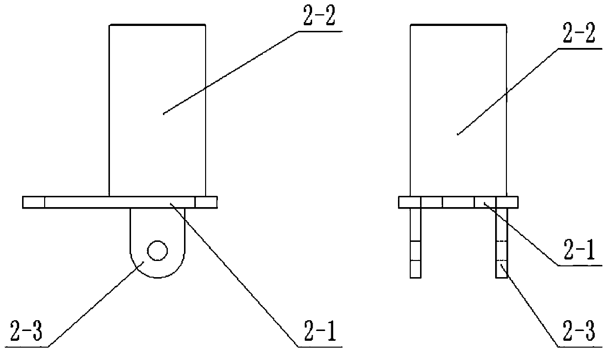
[0034] see image 3 , Leg 2 is made up of base plate 2-1, screw seat 2-2 and leg ear plate 2-3. The base plate 2-1 is a shaped steel plate, and the front portion is provided with a gap, and the swing bolt 1-3 can be snapped into it. The screw seat 2-2 is a circular steel pipe, which is provided with threads an...

Embodiment 2

[0037] The invention relates to a method for using a multi-working-condition movable traveling rail support device.

[0038] 1) According to the positions of the mounting holes at the four corners of the base plate 1-1, drill holes in the corresponding positions of the base, then install and fix the base 1 and the outrigger 2 on the base with expansion bolts, and snap the swing bolts 1-3 into the base plate 2-1 gap.

[0039] 2) Adjust the height of the nuts of the first swing bolts 1-3 so that the supporting leg 2 is in a vertical state.

[0040] 3) Rotate the lead screw 3-2 to the lead screw seat 2-2, install the bearing rail groove 3 on the leg 2, and rotate the lead screw 3-2 according to the laying height requirements of the running rail 4, so that the height of the bearing rail groove 3 Meet the needs.

[0041] 4) Open the clamping rail plates 3-3 on both sides, and place the running rail 4 so that the supporting rail plate 3-1 supports the running rail 4.

[0042] 5) ...


PUM


Abstract

The invention relates to the technical field of running rail supporting, in particular to a multi-loading-condition movable running rail supporting device and a using method. The multi-loading-condition movable running rail supporting device comprises a base, a supporting leg and a rail bearing tank. The base is composed of a base plate, a vertical plate and an eyelet bolt. The supporting leg is composed of a bottom plate, a lead screw base and lug plates. The rail bearing tank is composed of a rail bearing plate, a lead screw, rail clamping plates, an eyelet bolt and lug plates. Compared with the prior art, the multi-loading-condition movable running rail supporting device has the following major advantages that the adjustable base can meet the installation and usage requirement of substrates with inclined planes of different degrees; the supporting leg is connected with the rail bearing tank through the lead screw, and the height of the supporting leg can be adjusted, so that pavement of a running rail keeps smooth; and by fixing the running rail with the movable rail clamping plates, workloads are reduced, the mounting and dismounting efficiency is improved, and installation parts are prevented from being lost.

Description

[technical field] [0001] The invention relates to the technical field of traveling rail support, in particular to a multi-working-condition movable traveling rail supporting device and a usage method. [Background technique] [0002] At present, in the construction of urban rail projects in my country, simple and fixed support devices are usually used for laying temporary running rails. The base of this type of support device is a fixed angle and cannot be adjusted. Fix the rail with bolts, etc. This design has great limitations in use. First, the base of the fixed support device can only be installed on a base with a specific inclination angle, which limits its scope of use, or requires supports of various specifications. The device can meet the construction needs. my country's patent application number: CN201320266036.5 discloses a circular tunnel track-laying machine profile rail support. Although it can be adapted to circular tunnel installation, it cannot be suitable for ...

Claims


Application Information

Patent Timeline
Patent Type & Authority Patents(China)
IPC IPC(8): E01B29/04
CPCE01B29/04
Inventor 胡光静陈付平汪小俊刘绩赵文君
Owner (SUZHOU) RAIL TRANSIT SCI & TECH RES INST CO LTD SHANGHAI CIVIL ENG GRP OF CREC
Learn More