Multifunctional pedal extrusion type dehydration mop sink

An extruded, multi-functional technology, which is applied in water supply equipment, indoor sanitary pipeline installations, carpet cleaning, etc., can solve the problems of single material, high cost, and affecting smooth operation and safety, so as to avoid corrosion of parts and reduce Production cost, effect of extending service life

Inactive Publication Date: 2014-12-10
孟少甫
View PDF7 Cites 0 Cited by
  • Summary
  • Abstract
  • Description
  • Claims
  • Application Information

AI Technical Summary

Problems solved by technology

The product is bulky and occupies a large area, making it impossible to produce small-sized products suitable for civilian use
[0005] 3. attached Figure 10 And attached Figure 13 Most of the door-shaped pedal rods 106 set on the outer side walls of the lower pool 109 are exposed, and often rub against the surrounding objects during operation, which affects the smooth and safe operation, and is not conducive to the use and installation of the ceramic lower pool.
[0006] 4. attached Figure 14 Among them, the operation platform 101 above the back of the upper pool 107 has a complex structure and high cost. The upper pool water injection pipe 111 on the left side wall of the upper pool 107 cleaning area, when the water pressure is low, the water flow flows down the pool wall, and it is impossible to clean the mop. to clean
[0007] 5. attached Figure 11 , Figure 14 Among them, the water injection pipeline 111 for the upper pool and the water injection pipeline 102 for the lower pool are directly preset in the two side walls and the front wall of the upper pool 107, which brings inconvenience to the pipeline maintenance and disassembly
[0008] 6. Attached Figure 11 , Figure 13 and Figure 15 Among them, the design of the L-shaped communication pipe 110 with the lower pool 109 as an integral structure makes the lower pool only limited to the production of plastic molds, which is not conducive to ceramic production, and the material is single
And the stay rope 103 at the top of the drainage control valve valve stem 112 in the vertical pipeline passes upwards through the bottom of the upper pool 107, causing sewage to flow down to the outside of the pool along the stay rope 103 during operation, polluting the environment and pool body parts

Method used


Image

  • Multifunctional pedal extrusion type dehydration mop sink
  • Multifunctional pedal extrusion type dehydration mop sink
  • Multifunctional pedal extrusion type dehydration mop sink

Examples


Embodiment 1

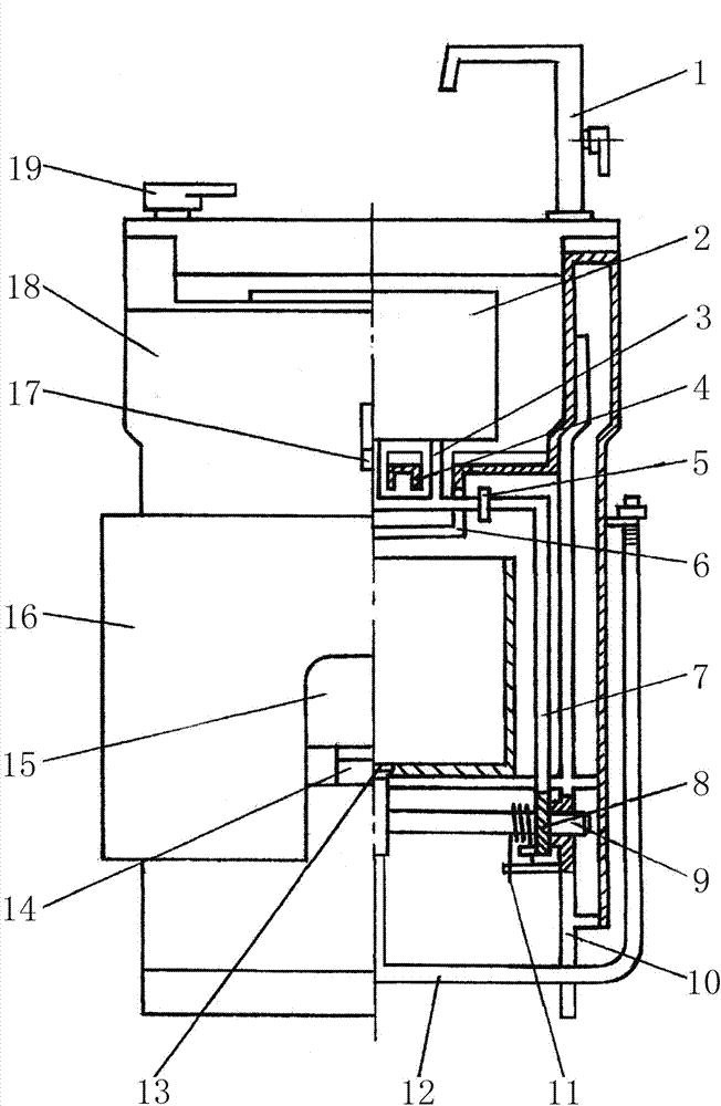
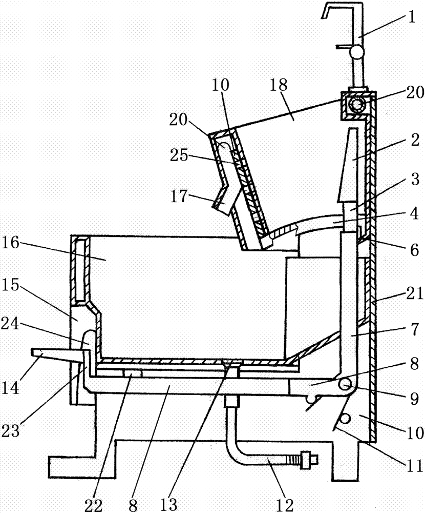
[0045] The pedal 14 of the pedal drive mechanism is connected with the upper end of the active link 23 arranged vertically, and the lower end of the active link 23 is connected with the front end of the square frame-shaped active arm 8 . The square frame-shaped active arm 8 is arranged below the lower pool 16, and the active connecting rod 23 is arranged in the hollow cavity of the lower pool front wall, and its activities are mainly carried out at the bottom of the lower pool 16, which reduces friction and collision with external objects. The special design scheme of the ceramic lower pool creates conditions for the use and installation of fragile parts such as ceramics. Limiting lever 22 has determined the limit position of safe and smooth movement of square frame-shaped active arm 8 upwards, and on the other hand has limited the height from the front end of the top surface of pedal 14 to the ground. The length of the frame-shaped slave arm 7 varies slightly depending on the...


PUM


Abstract

The invention discloses a multifunctional pedal extrusion type dehydration mop sink, which comprises a machine frame, an upper sink, a lower sink and a pedal driving mechanism, wherein a movable pressing plate is arranged in the upper sink; drainage slot holes are formed in the center of the bottom of the upper sink; the pedal driving mechanism comprises a driven connecting rod, a square driven arm, a square driving arm and a pedal; the driven connecting rod is arranged on the top of the square driven arm and penetrates through the drainage slot holes and is connected with the movable pressing plate; a water guiding dustpan is arranged on one side of the bottom of the upper sink on the upper part of the lower sink; and water guiding plates are arranged on two sides of the drainage slot holes at the bottom of the upper sink. According to the multifunctional pedal extrusion type dehydration mop sink, the movable pressing plate in the upper sink can extrude a mop for dehydration under the action of the pedal driving mechanism, and waste water flows into the lower sink for secondary utilization, so that water resources are saved; when a drainage valve is operated, hands are not wetted by water, so that the drainage valve is sanitary and convenient; products of various specifications can be made of materials such as ceramics, plastics, metals, so the multifunctional pedal extrusion type dehydration mop sink is simple in structure, practical and safe, and can meet demands of different occasions and people.

Description

technical field [0001] The invention relates to a household washing device, in particular to a multifunctional foot-operated squeezing type dehydration mop pool. Background technique [0002] The previous patent "Multi-functional mop cleaning and dehydrating machine" applied by myself, authorized announcement number: CN100459924C, during the trial production process of the prototype, the following deficiencies were found: [0003] 1. As attached Figure 10 , attached Figure 11 And attached Figure 12 As shown, when the mop is cleaned in the upper pool 107, the sewage splashes out from the side wall strip holes 105 of the two side walls, and also flows out laterally from the water outlet holes 108 at the bottom of the upper pool, thereby causing environmental pollution and product parts are easy to rust. [0004] 2. attached Figure 10 , attached Figure 12 And attached Figure 14 Among them, the upper pool 107 is bounded by the center line, the left side wall is provide...

Claims


Application Information

Patent Timeline
Patent Type & Authority Patents(China)
IPC IPC(8): E03C1/182A47L13/59
Inventor 孟少甫
Owner 孟少甫
Why Eureka
Try Eureka