
Cantilever type automatic marking equipment

A cantilever-type, automatic technology, applied in printing, power transmission devices, transfer materials, etc., can solve the problems of high cost of consumables, affecting the effect of printing marks, waste of resources, etc., achieve high repeat positioning accuracy, convenient operation and maintenance , the effect of reducing the floor area

Pending Publication Date: 2021-05-25
北京智棉科技有限公司
View PDF0 Cites 0 Cited by
  • Summary
  • Abstract
  • Description
  • Claims
  • Application Information

AI Technical Summary

Problems solved by technology

However, the frame-type brushing equipment is large in size and occupies a large area, which requires installation space and is not suitable for installation in a small space.
[0005] In addition, the existing automatic labeling equipment still has the following problems: ①The positioning mechanism and the control system are single-stage control modes, relying on the control of the movement of the cotton bale to achieve the relative position of the cotton bale and the nozzle, and the control accuracy is affected by the conveying speed of the cotton bale. It has a large impact and is not suitable for fast-speed bag delivery devices, and has poor adaptability; ②Both use rigid nozzles, which are difficult to adapt to cotton bales with inclined or uneven end faces, which will affect the effect of brushing marks; Waste, not only waste of resources, but also cause high cost of consumables for users

Method used


Image

  • Cantilever type automatic marking equipment
  • Cantilever type automatic marking equipment
  • Cantilever type automatic marking equipment

Examples


Embodiment Construction

[0028] 为使本发明的目的、技术方案和优点更加清楚,下面将结合附图对本发明的技术方案进行清楚、完整地描述。 Apparently, the described embodiments are some, but not all, embodiments of the present invention. Based on the embodiments of the present invention, all other embodiments obtained by persons of ordinary skill in the art without making creative efforts belong to the protection scope of the present invention.

[0029] 在本发明的描述中,需要说明的是,术语“上”、“下”、“内”、“外”等指示的方位或位置关系为基于附图所示的方位或位置关系,仅是为了便于描述本发明和简化描述,而不是指示或暗示所指的系统或元件必须具有特定的方位、以特定的方位构造和操作,因此不能理解为对本发明的限制。

[0030] In the description of the present invention, it should be noted that unless otherwise specified and limited, the terms "installation", "connection" and "connection" should be understood in a broad sense, for example, it can be a fixed connection or a detachable connection. Connected, or integrally connected; it can be mechanically connected or electrically connected; it can be directly connected or indirectly connected through an intermediary, and it can be the internal ...


PUM


Abstract

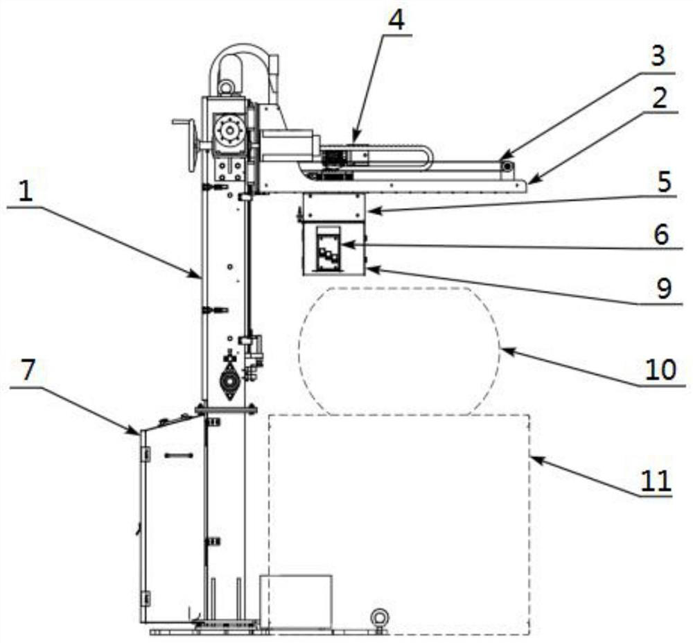
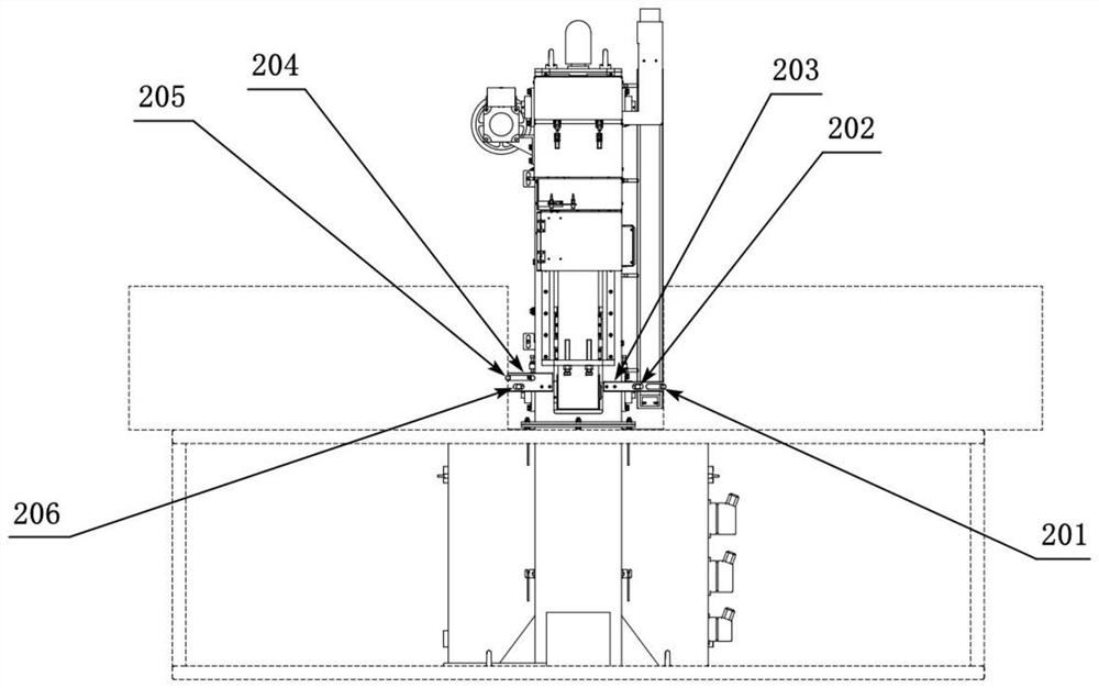
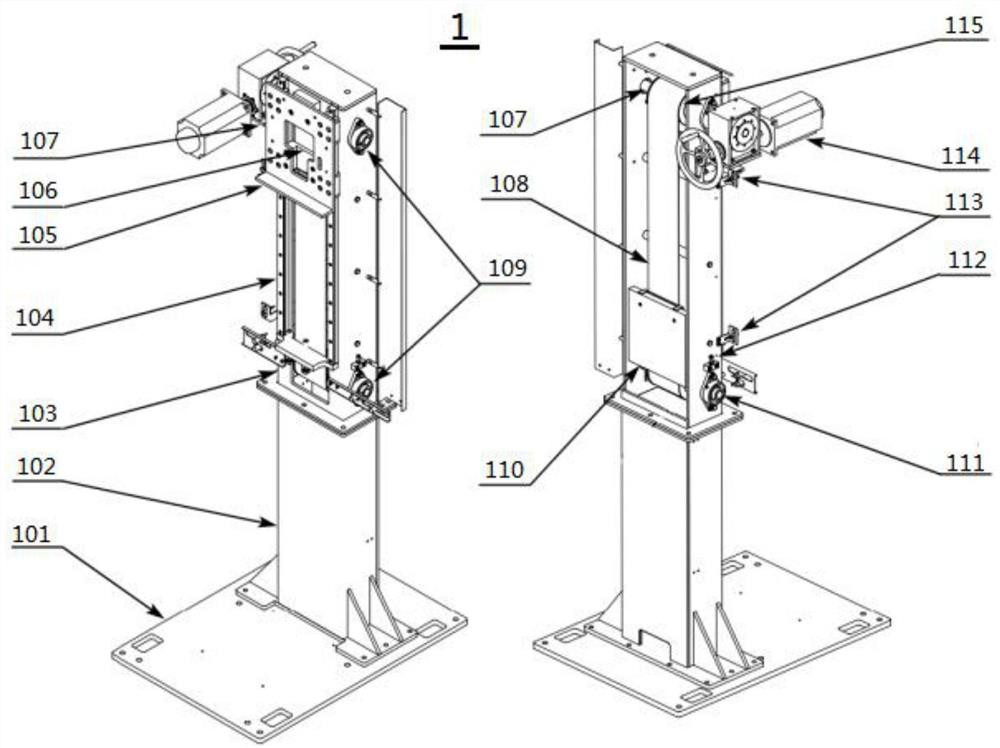
The invention relates to cantilever type automatic marking equipment. The equipment comprises a stand column and spray head lifting movement mechanism arranged at one side of a bale conveying device and provided with a lifting action end, a cantilever mounted at the lifting action end, a spray head horizontal movement mechanism mounted in the cantilever and provided with a horizontal action end, a spray head rotating mechanism mounted at the horizontal action end and provided with a rotating action end, a spray head feeding mechanism mounted at the rotating action end and provided with a feeding action end, and a flexible spray head mechanism mounted on the feeding action end. The whole marking machine adopts a cantilever type structural layout, integrates the advantages of a sinking type marking device and a frame type marking device, and is more reasonable in structure, small in occupied space, more convenient to install and maintain and lower in production and manufacturing cost; cotton bale and spray head two-stage control is originally created, cotton bale and spray head position control is more accurate, the equipment can be used for all users, and adaptability is higher; a flexible spray head is created for the first time, and the marking effect is good; and a connected ink supply mechanism is innovated, so that the consumable use cost of a user is greatly reduced.

Description

technical field [0001] The invention relates to a label brushing device, in particular to a cantilever type automatic label brushing device which integrates the advantages of two kinds of sinking type and frame type brushing equipment. Background technique [0002] At present, the existing automatic brushing equipment on the market mainly has two structural forms: submerged type and frame type. [0003] Submerged marking equipment refers to that the nozzle is installed in the lifting mechanism below the bale conveying device. During operation, the cotton bale is conveyed and passed over the nozzle. When the cotton bale is in place and the printing is started, the nozzle is lower than the cotton The position of the height of the bottom of the bag is raised to complete multi-line printing. Although the submersible brushing equipment has high integration, compact structure, small footprint, easy installation, and little impact on the original production line, it is inconvenien...

Claims


Application Information

Patent Timeline
IPC IPC(8): B41J2/01B41J3/407B41J25/00
CPCB41J2/01B41J3/4073B41J25/001
Inventor 李付堂吕德凯戎立斌侯学谦李峰华阿不都热西提·买买提杜卫东张娜汤明川李向军
Owner 北京智棉科技有限公司
Learn More