Friction pendulum isolation device

A pendulum and shock-isolation technology, which is applied to bridge parts, bridges, buildings, etc., can solve the problems of low reliability of damping energy-dissipating devices, large space occupation rate of damping energy-dissipating devices, and weak support structure stability. , to achieve the effect of preventing bridge beam drop, simple mechanism of shock absorption and isolation, and low space occupancy rate

Active Publication Date: 2017-05-10
ZHUZHOU TIMES NEW MATERIALS TECH
View PDF6 Cites 7 Cited by
  • Summary
  • Abstract
  • Description
  • Claims
  • Application Information

AI Technical Summary

Problems solved by technology

[0007] Aiming at the technical problems of large space occupancy rate of the damping energy-dissipating device, weak support structure stability and low reliability of the damping energy-dissipating device in the prior art, the present invention provides a friction pendulum type shock-isolating device, which is used in the friction pendulum The brake energy dissipation component is installed on the type vibration isolation support. The space occupation rate of the brake energy dissipation component is low, the structure is compact and stable, and the shock absorption and isolation mechanism is simple. It can effectively limit the horizontal sliding displacement of the friction pendulum type vibration isolation support and prevent Occurrence of falling bridge beams

Method used


Image

  • Friction pendulum isolation device
  • Friction pendulum isolation device
  • Friction pendulum isolation device

Examples


Embodiment Construction

[0022] Embodiments of the present invention will be described in detail below in conjunction with the accompanying drawings.

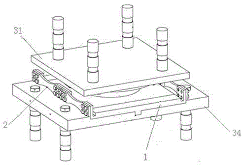
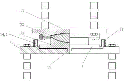
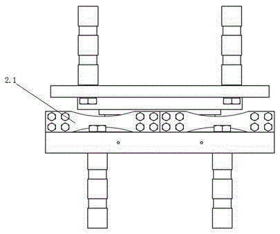
[0023] Such as Figure 1 to Figure 3 As shown, the friction pendulum type vibration isolation device includes a friction pendulum type vibration isolation support and a brake energy dissipation assembly. 32. The lower seat plate 33 and the bottom plate 34, the double spherical middle seat plate 32 and the upper seat plate 31 and the lower seat plate 33 respectively form a sliding spherical friction pair and a rotating spherical friction pair, and a plane is formed between the lower seat plate 33 and the bottom plate 34 Sliding friction pair, the center of the top surface of the bottom plate 34 is provided with a chute 35 arranged along the front and rear direction of the friction pendulum type shock-isolation bearing, and the bottom surface of the lower seat plate 33 has a guide rail that slides and fits with the chute 35;

[0024]The brake energy dis...


PUM


Abstract

A friction pendulum isolation device includes a friction pendulum isolation bearing and a brake energy dissipation assembly, wherein the friction pendulum isolation bearing comprises an upper seat plate, a double spherical surface middle seat plate, a lower seat plate and a bottom plate which are overlapped from top to bottom, the center of the top surface of the bottom plate is provided with a sliding groove arranged along the fore-and-aft direction of the friction pendulum isolation bearing, the brake energy dissipation assembly includes brake baffles and elastoplastic energy dissipation components, the two elastoplastic energy dissipation components are symmetrically arranged on the left and right sides of the lower seat plate and parallel with the sliding groove, the elastoplastic energy dissipation components are fixedly connected with the middle position, along the direction of the sliding groove, of the bottom plate, the brake baffles are arranged on the outer side of the lower seat plate and are fixed between the two elastoplastic energy dissipation components, the brake baffles are arranged on the bottom plate in a manner of being in slide fit with the sliding groove, the lower seat plate slides along the sliding groove to push the brake baffles to slide along the sliding groove so as to generate the tensile force along the direction of the sliding groove for the elastoplastic energy dissipation component. According to the friction pendulum isolation device, the brake energy dissipation assembly has low space occupation rate, compact and stable structure, and can effectively prevent the bridge falling beam phenomenon.

Description

technical field [0001] The invention belongs to the technical field of shock absorption and isolation of bridges, and in particular relates to a frictional pendulum type shock isolation device which not only has the function of energy consumption and shock absorption but also can prevent the phenomenon of falling beams. Background technique [0002] Under the action of earthquake, the falling beam of bridge superstructure is one of the main causes of bridge collapse. In order to solve the problem that the upper structure of the bridge is prone to falling beams, it is the simplest, economical and effective measure to set up the shock-absorbing and isolating bearings between the upper and lower structures of the bridge. The existing friction pendulum type shock-isolation bearings can be divided into two categories: one is fixed bearings, and the other is movable bearings. Under the earthquake, only a few of the fixed bearings can immediately start the shock absorption and iso...

Claims


Application Information

Patent Timeline
Patent Type & Authority Applications(China)
IPC IPC(8): E01D19/04
CPCE01D19/04E01D19/041
Inventor 王伟强张银喜罗勇欢曹志峰李世珩卜继玲
Owner ZHUZHOU TIMES NEW MATERIALS TECH
Why Eureka
Try Eureka