Stacked microstrip UHF antenna

A microstrip antenna and microstrip technology, applied in the direction of antenna, antenna grounding device, antenna grounding switch structure connection, etc., can solve the problem of miniaturization, low profile, light weight satellite communication antenna, mutual connection interface and cable occupying large space, Couplers and power division and phase-shifting networks have complex structures, and achieve the effects of compact and firm structure, guaranteed standing wave ratio and power capacity, and flexible and convenient debugging.

Pending Publication Date: 2018-09-14
南京乾波通信技术有限公司
View PDF0 Cites 12 Cited by
  • Summary
  • Abstract
  • Description
  • Claims
  • Application Information

AI Technical Summary

Problems solved by technology

Antennas working in the UHF frequency band, because the wavelength of the transmitted electromagnetic wave is about 1 meter, the height of the antenna is generally greater than a quarter of the wavelength (about 0.25 meters), which cannot meet the size requirements of airborne or missile-borne; therefore, the antenna The miniaturization, low profile, and light weight of the device have become the key points and difficulties in the design of satellite communication antennas
[0003] Microstrip antennas have many advantages such as low profile, light weight, easy processing, and low cost, and are widely used in the field of satellite communications; however, the existing microstrip antennas have the following defects: the shape of conventional single-layer antennas is still too large ; can not achieve multi-frequency characteristics; although it can work at multiple frequency points, the structure of the corresponding coupler and power division phase-shifting network is complex, and the interconnecting interfaces and cables occupy a large space, which is not conducive to realizing the miniaturization and low profile

Method used


Image

  • Stacked microstrip UHF antenna
  • Stacked microstrip UHF antenna
  • Stacked microstrip UHF antenna

Examples


Embodiment 1

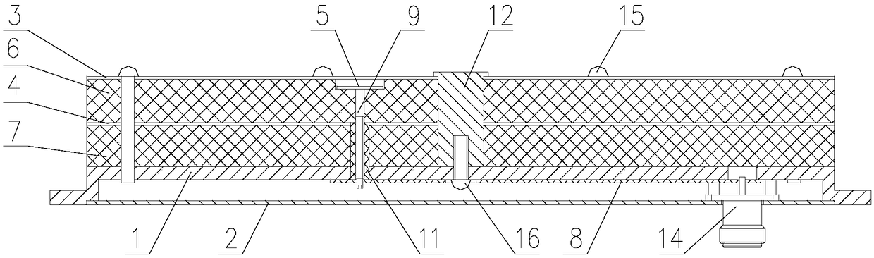
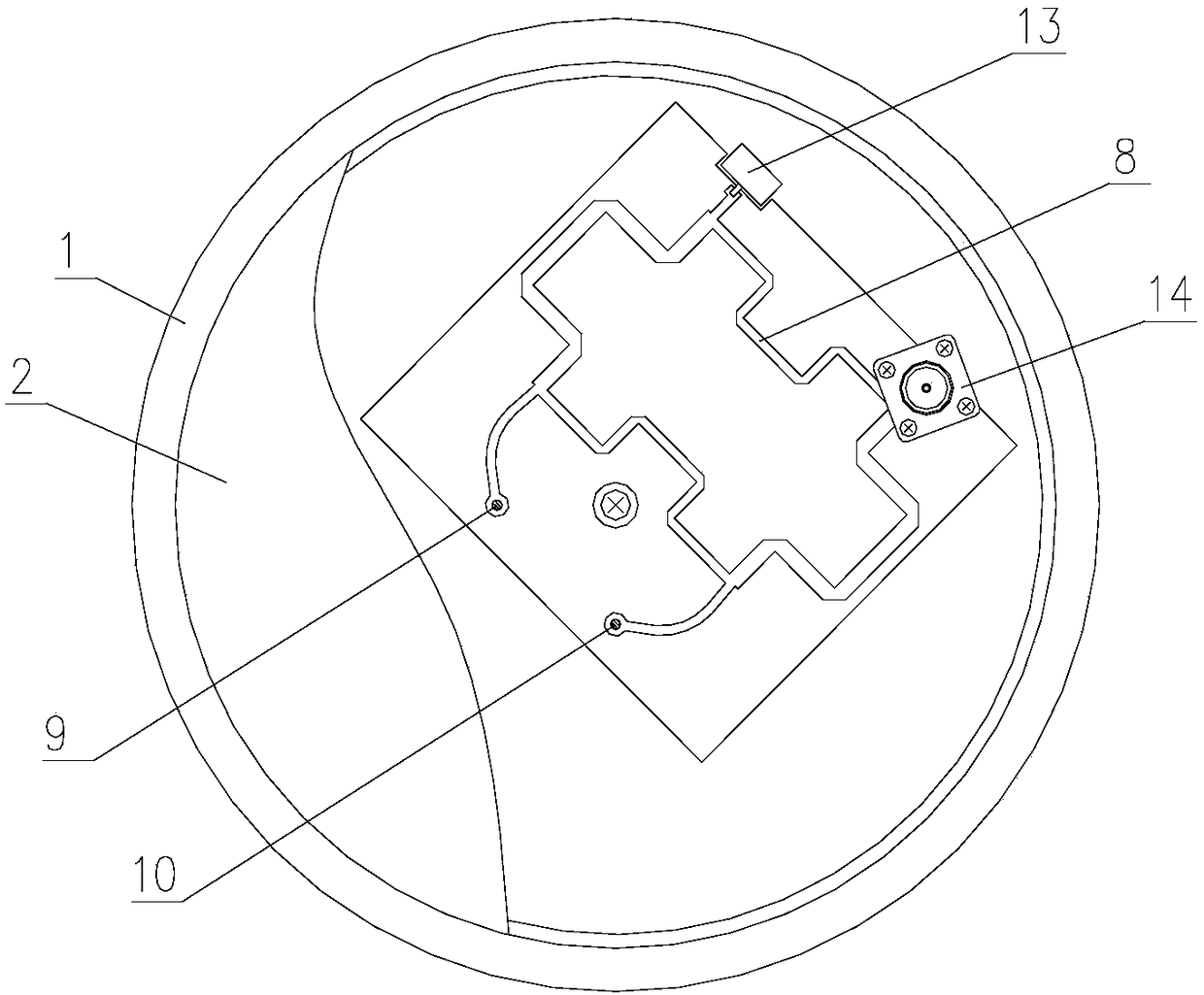
[0024] Embodiment 1: a kind of laminated microstrip UHF antenna, such as figure 1 and 2 As shown, it includes an antenna base 1 , a laminated microstrip antenna unit, a central column 12 , a feeding device and a shielding cover 2 .

[0025] The antenna base 1 is the carrier of the antenna device, and the antenna base 1 is a cavity disc structure. The stacked microstrip antenna unit is arranged on the upper surface of the antenna base 1, and is fixedly connected to the antenna base 1 through a central column 12 arranged at the center of the antenna base 1; the stacked microstrip antenna unit is surrounded by 8 first bolts 15 For fixed connection, the first bolt 15 is a metal bolt, which ensures the mechanical performance of the antenna device. Described central column 12 is the metal cylinder with flanging on the upper end, and the center of the lower end of central column 12 is provided with threaded hole, and the height of central column 12 is slightly less than the total t...


PUM


Abstract

The invention discloses a stacked microstrip UHF antenna which comprises an antenna base, a stacked microstrip antenna unit arranged on an upper surface of the antenna base and a feeding device connected to the stacked microstrip antenna unit. The stacked microstrip antenna unit comprises an upper radiation unit layer, an upper dielectric layer, a lower radiation layer and a lower dielectric layerfrom the top to bottom. The feeding device includes a coupling layer formed by two metal sheets arranged on an upper surface of the upper dielectric layer, a first feed probe and a second feed probeconnected to the coupling layer and a feeding network which is arranged in an inner cavity of the antenna base and is electrically connected to the first feed probe and the second feed probe. The stacked microstrip UHF antenna has the advantages of a compact structure, a small volume, a light weight, a low profile, a wide frequency band and convenience in installation and debugging.

Description

technical field [0001] The invention relates to a microstrip antenna, in particular to a laminated microstrip UHF antenna. Background technique [0002] At present, mobile satellite communication systems are widely used, and the application range of satellite communication antennas also covers vehicle, ship, airborne, and missile-borne applications. Airborne and missile-borne applications have high requirements for the weight and size of antennas. Antennas working in the UHF frequency band, because the wavelength of the transmitted electromagnetic wave is about 1 meter, the height of the antenna is generally greater than a quarter of the wavelength (about 0.25 meters), which cannot meet the size requirements of airborne or missile-borne; therefore, the antenna The miniaturization, low profile, and light weight of the device have become the key points and difficulties in the design of satellite communication antennas. [0003] Microstrip antennas have many advantages such as...

Claims


Application Information

Patent Timeline
Patent Type & Authority Applications(China)
IPC IPC(8): H01Q1/38H01Q1/48H01Q1/50H01Q5/20H01Q1/28
CPCH01Q1/38H01Q1/28H01Q1/48H01Q1/50H01Q5/20
Inventor 冯采丹项阳李卫忠
Owner 南京乾波通信技术有限公司
Why Eureka
Try Eureka