Capacitive loaded frequency conversion planar directional dual frequency antenna

A capacitive loading, dual-frequency antenna technology, applied to antennas, devices that enable antennas to work in different bands at the same time, circuits, etc., can solve the problems of inflexible applications and complex structures, and achieve frequency conversion work, simple control, and simple structure Effect

Active Publication Date: 2019-01-22
SYSU CMU SHUNDE INT JOINT RES INST +1
View PDF5 Cites 0 Cited by
  • Summary
  • Abstract
  • Description
  • Claims
  • Application Information

AI Technical Summary

Problems solved by technology

[0003] Aiming at the shortcomings of the prior art, such as complex structure and inflexible application, the present invention provides a capacitive-loaded frequency-changing planar directivity dual-frequency antenna that is easy to process, miniaturized, and has good planar directivity and gain.

Method used


Image

  • Capacitive loaded frequency conversion planar directional dual frequency antenna
  • Capacitive loaded frequency conversion planar directional dual frequency antenna
  • Capacitive loaded frequency conversion planar directional dual frequency antenna

Examples


Embodiment Construction

[0018] The present invention will be further described below in conjunction with the accompanying drawings, but the embodiments of the present invention are not limited thereto.

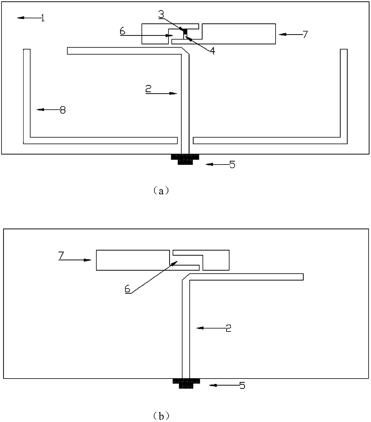
[0019] In the figure, 1-dielectric plate, 2-DSPSL dipole, 3-chip capacitor, 4-PIN diode, 5-feed connector, 6-slot structure, 7-rectangular metal radiator, 8-reflecting patch.

[0020] A capacitively loaded frequency-changing planar directional dual-frequency antenna, as attached figure 1 As shown, the antenna is a planar structure, including a dielectric plate 1, a DSPSL dipole 2, a patch capacitor 3, a PIN diode 4, a feed connector 5, a rectangular metal radiator 7 and a reflective patch 8; the rectangular metal radiator 7 There is a slit structure 6 on the top, the DSPSL dipole 2 and the rectangular metal radiator 7 are symmetrically printed on the upper and lower sides of the dielectric board 1, and the chip capacitor 3, the PIN diode 4, and the reflective patch 8 are printed on the upper surface ...


PUM


Abstract

The invention provides a capacitor-loaded variable-frequency planar directional dual-frequency antenna having advantages of easy processing, miniaturization, high directivity, and good gain. The antenna is composed of a dielectric plate, a DSPL dipole, a chip capacitor, a PIN diode, a feed connector, rectangular metal radiators, and slit structures formed in the middle of the rectangular metal radiators. The rectangular metal radiators are arranged at the upper surface and the lower surface of the dielectric plate symmetrically; the chip capacitor and the PIN diode are connected in series and are welded in the slit structure of the rectangular metal radiator on the upper surface; a central feed pin of the feed connector is connected with the upper surface of a microstrip line of the DSPL dipole; and outer conductor of the feed connector is connected with the lower surface of the microstrip line of the DSPL dipole. According to the invention, a reflection paster is arranged on the upper surface, so that the antenna has the certain directivity; conduction of the PIN diode switch is controlled based on external direct currents, so that the loading states of the capacitor on the antenna is controlled to achieve an objective of frequency conversion.

Description

technical field [0001] The present invention relates to the radio field, and more specifically, relates to a capacitance-loaded frequency-changing planar directional dual-frequency antenna. Background technique [0002] With the rapid development of wireless communication technology, mobile terminals are constantly developing. Due to the different operating frequencies of various communication standards, the antennas of mobile terminals often need to support multiple operating frequency bands at the same time. The coverage bandwidth of traditional broadband antennas can no longer meet the requirements. , so multi-frequency antennas with adjustable functions are more beneficial in practical applications. Contents of the invention [0003] Aiming at the defects of complex structure and inflexible application in the prior art, the present invention provides a capacitive-loaded frequency conversion planar directivity dual-frequency antenna that is easy to process, miniaturized...

Claims


Application Information

Patent Timeline
Patent Type & Authority Patents(China)
IPC IPC(8): H01Q1/38H01Q13/08H01Q15/14H01Q5/20
CPCH01Q1/38H01Q5/20H01Q13/08H01Q15/14
Inventor 邓创李元新叶道峰龙云亮
Owner SYSU CMU SHUNDE INT JOINT RES INST
Why Eureka
Try Eureka