
Multi-point type sliding lock system for cabinet body

A multi-point, cabinet technology, used in padlocks, building locks, buildings, etc., can solve the problems of cumbersome operation of opening or closing products, slowing down production efficiency, and rising costs, and achieves superior anti-theft performance, simple structure, and easy operation. quick effect

Pending Publication Date: 2017-05-10
中山基龙工业有限公司
View PDF0 Cites 2 Cited by
  • Summary
  • Abstract
  • Description
  • Claims
  • Application Information

AI Technical Summary

Problems solved by technology

[0002] Nowadays, locks are used in tool cabinets, lockers and other cabinets for anti-theft. A lock of the existing cabinet can only lock one point. If the product size is relatively large, in order to ensure the lock function and lock effect, The number of locking points needs to be increased, and the number of lock accessories and locks needs to be increased accordingly, which will increase the cost and slow down the production efficiency; and the operation is cumbersome when the user opens or closes the product

Method used


Image

  • Multi-point type sliding lock system for cabinet body
  • Multi-point type sliding lock system for cabinet body
  • Multi-point type sliding lock system for cabinet body

Examples


Embodiment Construction

[0014] Below in conjunction with specific embodiment, further illustrate the present invention. It should be understood that these examples are only used to illustrate the present invention and are not intended to limit the scope of the present invention. In addition, it should be understood that after reading the teachings of the present invention, those skilled in the art can make various changes or modifications to the present invention, and these equivalent forms also fall within the scope defined by the appended claims of the present application.

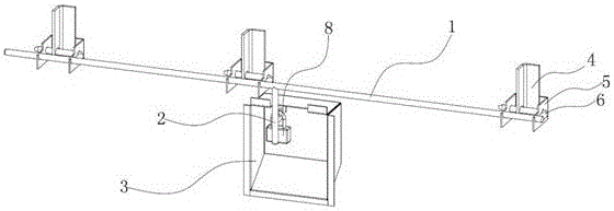
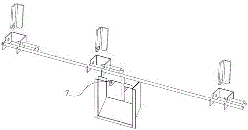
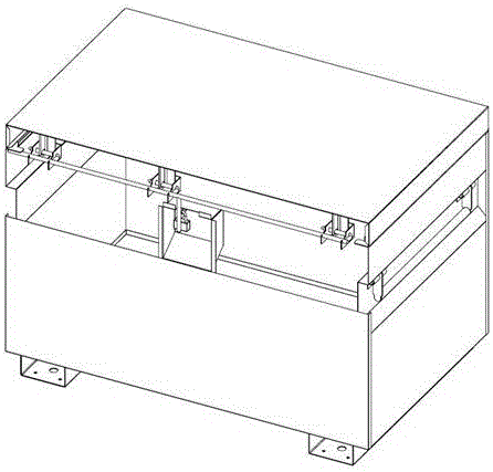
[0015] like Figure 1-5 As shown, the embodiment of the present invention relates to a multi-point sliding lock system for a cabinet body, including a lock bar iron bar 1, a lock hook member 4 and a lock bar 6, and the lock bar iron bar 1 is horizontally slid and erected on On several locking bar fixing blocks 5 evenly arranged inside the upper end of the front side of the cabinet body, lock hooks 4 are arranged at positions c...


PUM


Abstract

The invention relates to a multi-point type sliding lock system for a cabinet body. The multi-point type sliding lock system comprises locking bar iron rods, lock hook parts and lock rods. The locking bar iron rods are transversely erected on a plurality of locking bar fixing blocks in a horizontal sliding manner, wherein the locking bar fixing blocks are uniformly arranged on the inner side of the upper end of the front side of the cabinet body. The lock hook parts are arranged in positions, corresponding to the lock bar fixing blocks, of the inner side of the front end of an upper cover of the cabinet body. The lock rods are horizontally arranged in the positions, corresponding to the lock bar fixing blocks, of the inner side walls of the lock bar iron rods. A lock cover with the front end opened is installed on the upper side of the front end of the cabinet body. Lock bar push rods vertically extending into the lock cover downwards are arranged in the middle portions of the lock bar iron rods. Corresponding padlock plates are uniformly distributed on the side walls of the lock bar push rods and the inner side wall of the lock cover. A padlock penetrates the padlock plates. The multi-point type sliding lock system is simple in structure and fast to operate, the multi-point lock effect is achieved by increasing the number of lock bar inserting strips and the number of the lock bar fixing blocks, and the system cannot be disassembled with force by means of common blasting disassembling tools, and is excellent in anti-theft performance and fashionable and attractive in appearance.

Description

technical field [0001] The invention relates to the field of cabinet locks, in particular to a multi-point sliding lock system for a cabinet. Background technique [0002] Nowadays, locks are used in tool cabinets, lockers and other cabinets for anti-theft. A lock of the existing cabinet can only lock one point. If the product size is relatively large, in order to ensure the lock function and lock effect, The number of locking points needs to be increased, and the number of lock accessories and locksets needs to increase accordingly, which increases the cost and slows down the production efficiency; moreover, it is cumbersome for the user to open or close the product. Contents of the invention [0003] The technical problem to be solved by the present invention is to provide a multi-point slide lock system for the cabinet body, which has a simple structure and quick operation, and can achieve the effect of locking multiple points by increasing the number of lock bar insert...

Claims


Application Information

Patent Timeline
Patent Type & Authority Applications(China)
IPC IPC(8): E05B65/52E05B63/14E05B15/02E05B15/10E05B67/38
CPCE05B15/0205E05B15/108E05B63/146E05B65/5238E05B67/383E05B2015/023
Inventor 翁荣波李健财
Owner 中山基龙工业有限公司
Learn More