Method of cleaning diesel particulate filters

A technology for particulate filters, diesel engines, applied in cleaning methods and utensils, membrane filters, chemical instruments and methods, etc., and can solve problems such as unsatisfactory

Inactive Publication Date: 2017-05-10
CATERPILLAR INC
View PDF1 Cites 0 Cited by
  • Summary
  • Abstract
  • Description
  • Claims
  • Application Information

AI Technical Summary

Problems solved by technology

However, this particular method may not be very satisfactory as accumulated particulates may not be sufficiently removed by the pressurized air

Method used


Image

  • Method of cleaning diesel particulate filters
  • Method of cleaning diesel particulate filters
  • Method of cleaning diesel particulate filters

Examples


Embodiment Construction

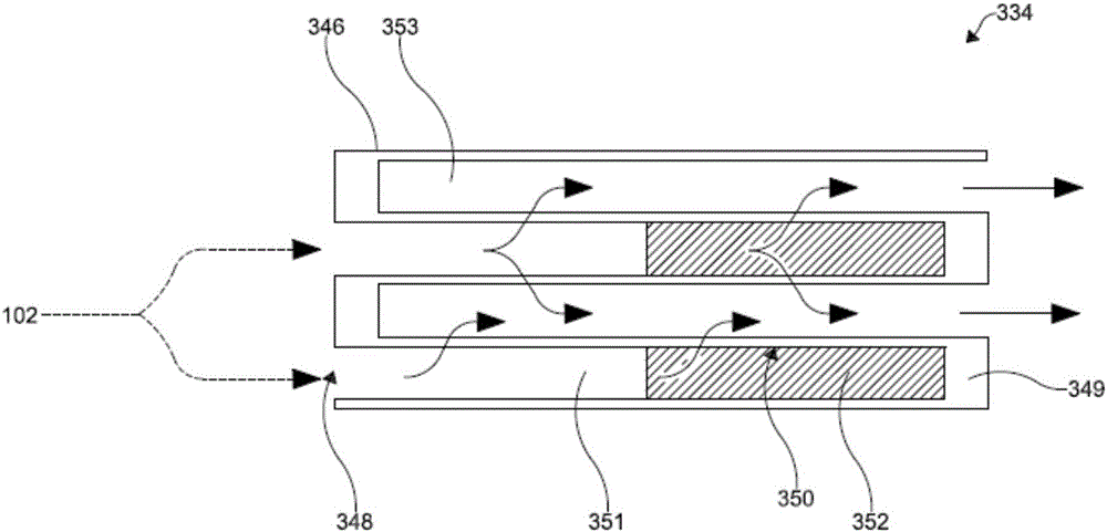
[0018] The present disclosure relates to a system and method for removing particulates accumulated in a DPF through the use of blocking agents. According to various aspects of the methods disclosed herein, blocking agents can be selectively applied to the filter media of the DPF. A DPF particle removal process with pneumatic air knives can be used to remove particles. In this way, the blocking agent can block the air flow of the air knife and thereby redirect and focus the air flow in the area of ​​the DPF filter wall that is not blocked. After removal of the microparticles, the blocking agent can be removed.

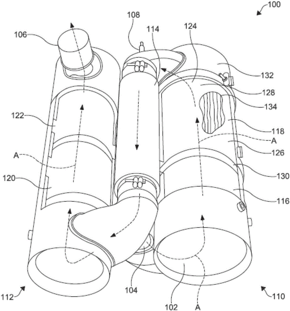
[0019] Such as figure 1 As shown in , an aftertreatment system 100 may be configured to limit or remove particulate matter in an engine exhaust stream 102 . The aftertreatment system 100 may include a system inlet 104 for an engine exhaust flow 102 from an internal combustion engine (not shown), a system outlet 106 , a reductant supply 108 , a first housing 110 , and...


PUM


Abstract

A method of removing or reducing the particulate buildup within the diesel particulate filter of an aftertreatment system includes the selective application of a blocking agent to a filter medium of the diesel particulate filter, displacement of the particulate from the filter medium using a fluid stream, and subsequent removal of the blocking agent.

Description

technical field [0001] The present disclosure relates generally to methods of cleaning internal combustion engine components, and more particularly to methods of removing particulates that accumulate on diesel particulate filters. Background technique [0002] Combustion of fuel in an internal combustion engine system typically emits a complex mixture of chemicals in its exhaust stream. Emissions from these engines can contain organic and inorganic particulate matter such as soot, sulfates, soluble organic fractions, and ash. To reduce the levels of these chemicals in engine emissions, internal combustion engine systems have aftertreatment systems. A diesel particulate filter (DPF) represents a component of an aftertreatment system for removing and / or reducing diesel particulate matter from an exhaust stream. DPFs can be used to capture these particulate matter resulting from combustion, thereby limiting the amount of soot and other particulate matter emitted into the envi...

Claims


Application Information

Patent Timeline
Patent Type & Authority Applications(China)
IPC IPC(8): F01N3/023
CPCF01N3/0232F01N3/0233B01D2279/30F01N3/05F01N3/103F01N3/106F01N3/2066F01N3/2828F01N3/2892F01N3/022F01N2240/20F01N2260/04F01N2330/60F01N2610/02F01N2610/1453F01N13/009F01N3/0237F01N3/035F01N2260/06Y02T10/12B01D46/84B08B7/04
Inventor S·梅斯特S·科内尔J·库珀D·迪尔斯
Owner CATERPILLAR INC
Why Eureka
Try Eureka