Centrifugal fan and dust collector provided with same

A centrifugal fan and fan cover technology, which is applied in the direction of machines/engines, mechanical equipment, liquid fuel engines, etc., can solve the problems of large loss, long air flow process, and long follow-up process, so as to reduce air flow loss, reduce process flow, and improve efficiency effect

Active Publication Date: 2017-05-10
MIDEA GRP CO LTD
View PDF7 Cites 14 Cited by
  • Summary
  • Abstract
  • Description
  • Claims
  • Application Information

AI Technical Summary

Problems solved by technology

Because the centrifugal fan used for the vacuum cleaner needs to increase the pressure rise of the centrifugal fan as much as possible under the limited speed, so as to increase the vacuum degree of the inlet of the centrifugal fan. A diffuser in the form of a single arc or a single row of double arcs will result in a longer airflow process. After the airflow passes through the diffuser to decelerate and diffuse, the outlet airflow angle of the diffuser is still small, and the airflow velocity at the outlet of the diffuser is still relatively small. It is still high, and after the airflow leaves the diffuser, the follow-up process is longer and the loss is larger, resulting in the low efficiency of the centrifugal fan, which in turn reduces the efficiency and energy efficiency level of the vacuum cleaner

Method used


Image

  • Centrifugal fan and dust collector provided with same
  • Centrifugal fan and dust collector provided with same
  • Centrifugal fan and dust collector provided with same

Examples


Embodiment Construction

[0030] Embodiments of the present invention are described in detail below, examples of which are shown in the drawings, wherein the same or similar reference numerals designate the same or similar elements or elements having the same or similar functions throughout. The embodiments described below by referring to the figures are exemplary only for explaining the present invention and should not be construed as limiting the present invention.

[0031] In describing the present invention, it should be understood that the terms "center", "longitudinal", "transverse", "length", "width", "thickness", "upper", "lower", "front", " Back", "Left", "Right", "Vertical", "Horizontal", "Top", "Bottom", "Inner", "Outer", "Clockwise", "Counterclockwise", "Axial" , "radial", "circumferential" and other indicated orientations or positional relationships are based on the orientations or positional relationships shown in the drawings, which are only for the convenience of describing the present ...


PUM


Abstract

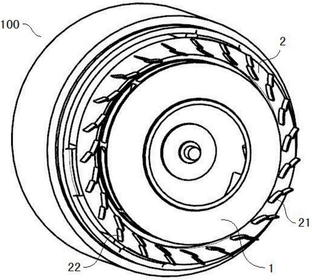
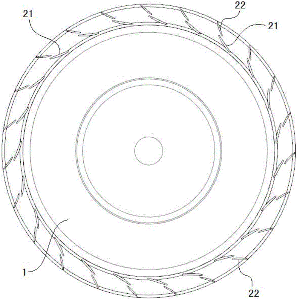
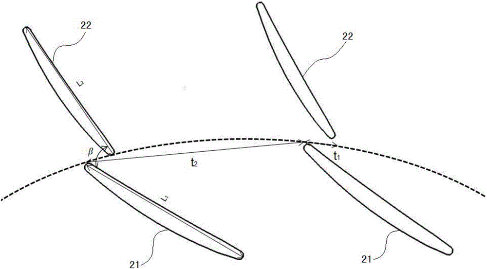
The invention discloses a centrifugal fan and a dust collector provided with the same. The centrifugal fan comprises an impeller and a pressure expander. The pressure expander is arranged on the periphery of the impeller. The pressure expander comprises a plurality of rows of blade sets arranged sequentially from inside to outside. Each row of blade sets comprises a plurality of blades arranged at intervals in the peripheral direction of the impeller. The blades in the multiple rows of blade sets correspond in a one-to-one correspondence mode. At least one row of blades, located on the inner side of the impeller, of the multiple rows of blade sets, deviates from the radial direction of the impeller. The included angles, between the blades in the multiple rows of blade sets and a datum line, from inside to outside are gradually decreased. The datum line is a line connecting the inner ends of the blades in the row, at the innermost side, of the multiple rows of blade sets and the center of the impeller. According to the centrifugal fan, by arranging the multiple rows of blade sets sequentially from inside to outside, the included angles between the blades of the multiple rows of blade sets and the datum line are gradually decreased from inside to outside, airflow can be forced to flow in the radial direction of the impeller, the number of procedures can be decreased, the airflow loss of the centrifugal fan can be reduced, and the efficiency of the centrifugal fan is improved.

Description

technical field [0001] The invention relates to the technical field of fan manufacturing, in particular to a centrifugal fan and a vacuum cleaner with it. Background technique [0002] In the related art, the main structural form of the centrifugal fan used for the vacuum cleaner is the structural form of impeller+diffuser+refluxer, wherein the diffuser is usually in the form of single arc, double arc or airfoil. Because the centrifugal fan used for the vacuum cleaner needs to increase the pressure rise of the centrifugal fan as much as possible under the limited speed, so as to increase the vacuum degree of the inlet of the centrifugal fan. A diffuser in the form of a single arc or a single row of double arcs will result in a longer airflow process. After the airflow passes through the diffuser to decelerate and diffuse, the outlet airflow angle of the diffuser is still small, and the airflow velocity at the outlet of the diffuser is still relatively small. It is still hig...

Claims


Application Information

Patent Timeline
Patent Type & Authority Applications(China)
IPC IPC(8): F04D29/44
CPCF04D29/444Y02E10/72
Inventor 明乐乐张朝磊张辉
Owner MIDEA GRP CO LTD
Why Eureka
Try Eureka