A linear linkage expansion device

A technology of telescopic device and driving device, which is applied in the direction of transmission device, belt/chain/gear, mechanical equipment, etc., can solve the problems that the telescopic speed and telescopic distance are not taken into account at the same time, the number of telescopic sections cannot be adjusted, and the number of sections is fixed, etc. Conducive to mass production, increased telescopic length, easy to install and use

Inactive Publication Date: 2019-04-16
宿州学院
View PDF5 Cites 0 Cited by
  • Summary
  • Abstract
  • Description
  • Claims
  • Application Information

AI Technical Summary

Problems solved by technology

However, in the existing mechanical telescopic devices, the telescopic speed and telescopic distance are generally not taken into consideration at the same time, and the stability of the telescopic process needs to be enhanced.
[0004] Therefore, there are the following three problems that need to be solved or improved in the existing mechanical telescopic devices: (1) the number of nodes is fixed, and the required number of telescopic nodes cannot be adjusted as required; Instability caused by changes; (3) The scaling speed problem during long-distance scaling

Method used


Image

  • A linear linkage expansion device
  • A linear linkage expansion device
  • A linear linkage expansion device

Examples


Embodiment 1

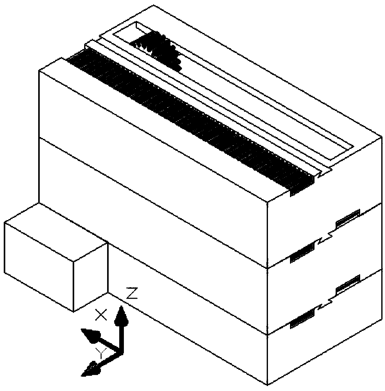
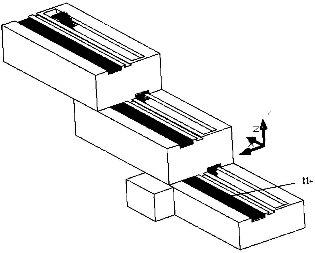
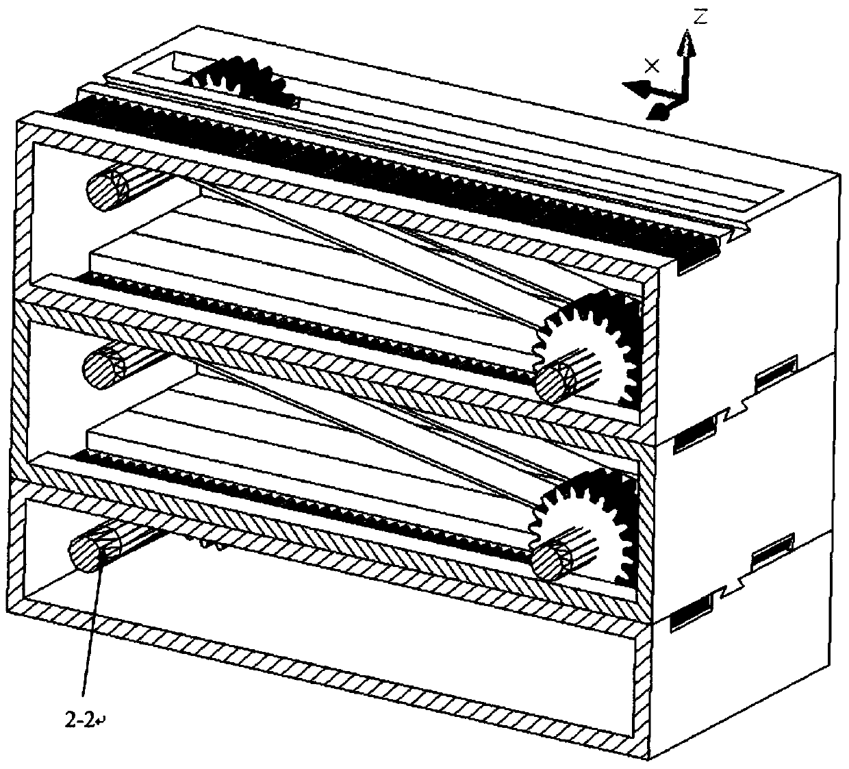
[0040] Such as figure 1 The above is an overall schematic diagram of the linear linkage expansion device of the present invention. The telescopic device in this embodiment is made of two-stage slide blocks. refer to image 3 , Figure 4 and Figure 6 The labels of each structure are: base 1, motor 2-1, motor drive shaft 2-2, transmission gear 2-3, rack 11 on the upper surface of the base, rack 3 on the upper surface of the slider, and rack on the lower surface of the slider 5. Lower slider linkage gear shaft 8, slider lower linkage gear 7, synchronous belt 10, slider upper linkage gear shaft 9, slider upper linkage gear 6, slider upper surface slot 2, slider lower surface slot 4. The guide protrusion 13 on the lower surface of the slider, and the guide groove 12 on the upper surface of the slider.

[0041] The guide projection and the guide groove in this embodiment have trapezoidal cross-sections. Such a design can ensure that the sliding direction of the sliders does n...

Embodiment 2

[0051] A linear linkage telescoping device, comprising a driving device and at least two stages of sliders, the driving device drives the first stage of sliders to slide, characterized in that the sliders of each stage have the same structure and are stacked step by step;

[0052] The upper surfaces of the sliders at all levels are provided with slots 2 on the upper surface and racks 3 on the upper surface along the overall expansion and contraction direction of the device; The lower surface slot 4 and the lower surface rack 5 are provided; the lower surface slot 4 of the slider of this stage is set opposite to the upper surface rack 3 of the upper slider, and the upper surface slot 2 of the slider of the current stage is connected with The rack 5 on the lower surface of the next-level slider is relatively arranged;

[0053] The insides of the sliders at all levels are provided with upper linkage gears 6 that pass through the slots 2 on the upper surface; the interiors of the ...


PUM


Abstract

The invention provides a linear superposed large scope fast telescopic device. The device comprises a pedestal and at least two stages of slide blocks. A gear which is located in the pedestal and connected with a motor drives the slide blocks to slide. The slide blocks are stacked on the pedestal stage by stage. The linkage relationship between the slide blocks is formed through meshing of gears and racks of the upper and lower stages of slide blocks. According to the telescopic device, different extension-and-retraction amount and different extension-and-retraction speed can be obtained by selecting the quantity of the stacked slide blocks. The extension-and-retraction directions of all stages of slide blocks are identical. The extension-and-retraction amount can be decided by the number of stages of the slide blocks. The linear linkage telescopic device overcomes the structural instability caused by the situation that in the prior art, power equipment needs to extend or retract with the device, and accordingly the position of the power equipment is changed. Through keeping the power equipment in an unchanged position of the fixed pedestal, because of the linkage relationship between the upper and lower stages of slide blocks, the power is transmitted and outputted to each stage of slide block, thus not only the precise control of the extension-and-retraction amount can be achieved, but also at the same time, the stability of the whole device is maintained.

Description

technical field [0001] The invention relates to the structural field of mechanical operating devices, in particular to a device structure for telescopic operation mainly used in narrow environments. Background technique [0002] Currently existing mechanical telescopic devices (excluding hydraulic and pneumatic telescopic devices) basically adopt the principle of two-way telescopic expansion, that is, fix the middle rod and expand and contract both ends at the same time, and the number of joints is often fixed at two or three. Therefore, the existing mechanical telescopic devices generally have the problem that the position of the driving unit changes during the telescopic process. The unfixed drive has a serious negative effect on the stability of the telescoping process. In addition, the existing mechanical telescoping devices are prone to breakage when performing rapid telescoping, so when telescoping over a long distance, they can only adapt to a slow telescoping speed,...

Claims


Application Information

Patent Timeline
Patent Type & Authority Patents(China)
IPC IPC(8): F16H37/02
CPCF16H37/02
Inventor 李明纵榜峰
Owner 宿州学院
Why Eureka
Try Eureka