Lubricating oil circuit structure for heavy-duty transmission gear bearings of aeroengine

An aero-engine, heavy-duty transmission technology, applied in the direction of gear lubrication/cooling, transmission parts, belts/chains/gears, etc., can solve the reliability reduction of gear transmission system, insufficient injection lubrication scheme, and unsatisfactory lubrication effect, etc. problem, to achieve the effect of simple and ingenious structure, good lubrication effect and weight reduction

Inactive Publication Date: 2017-05-10
CHENGDU ENGINE GROUP
View PDF3 Cites 12 Cited by
  • Summary
  • Abstract
  • Description
  • Claims
  • Application Information

AI Technical Summary

Problems solved by technology

Since the bearings at both ends need two nozzles, it is necessary to reserve space for the nozzles in the design of the gearbox, and the variable speed gearbox is usually a two-lobed structure in the middle, in order to ensure that the lubricating oil flow path is designed in the gearbox shell , will inevitably lead to a complex structure of the gearbox and an increase in weight
In addition, if the bearing is lubricated by spraying, the lubricating oil is not easy to enter the lubricating surface, the lubricating effect is not satisfactory, and the reliability of the gear transmission system is reduced
In view of the insufficient injection lubrication scheme of the bearings at both ends of the heavy-duty gear in the prior art, it needs to be improved in design

Method used


Image

  • Lubricating oil circuit structure for heavy-duty transmission gear bearings of aeroengine
  • Lubricating oil circuit structure for heavy-duty transmission gear bearings of aeroengine
  • Lubricating oil circuit structure for heavy-duty transmission gear bearings of aeroengine

Examples


Embodiment 1

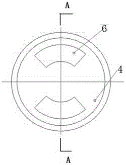
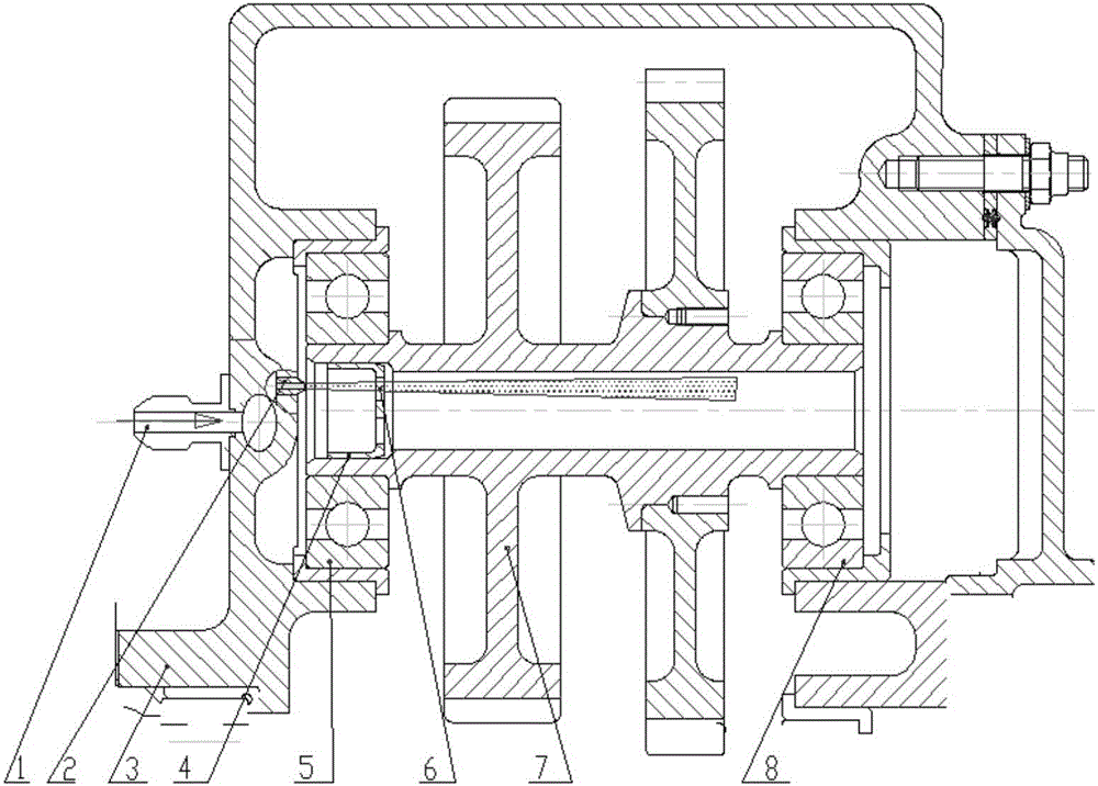
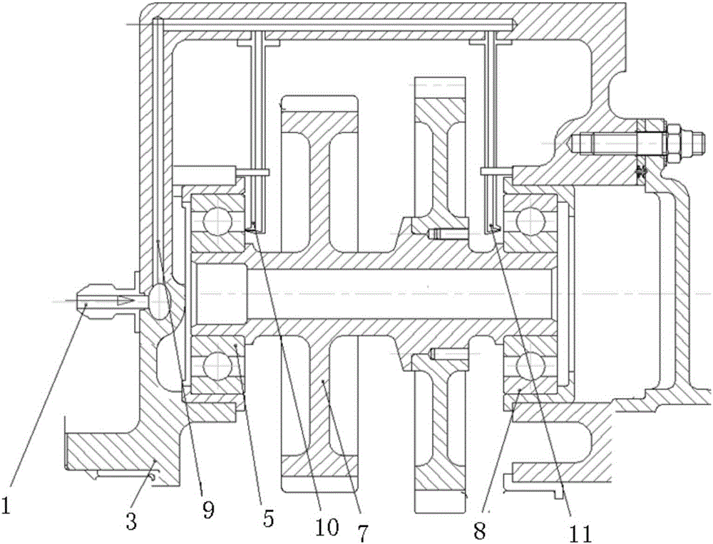
[0021] The lubricating oil circuit structure of the aero-engine heavy-duty transmission gear bearing described in this embodiment is as follows: figure 1 , Figure 3-1 , Figure 3-2 , Figure 4 and Figure 5 , which is composed of: a chamber is designed at one end of the shaft hole of the hollow gear shaft 7 installed in the gearbox 3 through bearings, and a lubricating oil flow distributor 4 is placed in the chamber, and the lubricating oil flow distributor is opposite to the gearbox. The lubricating oil nozzle 2 is set at the position, and the flow distributor 4 is a bushing sleeve designed with a through-flow hole 6 at the bottom of the cylinder. On the rotating annular surface of the bottom of the tube, the shape of the flow hole is a structure hole of the fan ring surface. There are two flow holes on the fan ring surface of the same shape, which are symmetrically arranged on the ring surface of the same diameter at the bottom of the cylinder. The area of ​​the torus ...


PUM


Abstract

The invention provides a lubricating oil circuit structure for heavy-duty transmission gear bearings of an aeroengine. According to the lubricating oil circuit structure for the heavy-duty transmission gear bearings of the aeroengine, a cavity is designed in one end of a shaft hole of a hollow gear shaft which is mounted in a gearbox through the bearings, a lubricating oil flow distributor is arranged in the cavity, and a lubricating oil nozzle is arranged in the position, opposite to the lubricating oil flow distributor, of the gearbox; pressure lubricating oil enters the distributor from the nozzle, part of the lubricating oil is sputtered back through the distributor and squeezed into a near-end bearing lubricating surface under the effect of centrifugal force so as to lubricate and cool the near-end bearing, and the other part of the lubricating oil enters the shaft hole of the hollow gear shaft through the orifice of a through flow hole of the distributor, flows towards the far-end bearing and is squeezed into a far-end bearing lubricating surface under the effect of the centrifugal force so as to lubricate and cool the far-end bearing. By adoption of the lubricating oil circuit structure for the heavy-duty transmission gear bearings of the aeroengine, the structure of the gearbox is simplified, the weight of the gearbox is reduced, and the gear bearing lubricating effect and the reliability of a gear transmission system are improved.

Description

technical field [0001] The invention relates to a gear bearing lubricating technology of an aero-engine transmission system, in particular to a heavy-duty transmission gear bearing lubricating and oiling path structure in which the gear box has a two-lobe structure. Background technique [0002] The aero-engine gear transmission system is a heavy-duty transmission system, the transmission power is above 200 kilowatts, and the radial force on the gear shaft can reach more than 5000N. Therefore, the lubrication and cooling of the bearings at both ends of the heavy-duty gear is very important, which is related to the bearing stable operation and service life. Reasonable design of the lubrication path of the bearings at both ends of the heavy-duty gear is an important design content of the aero-engine gear transmission system. [0003] For the lubrication of the bearings at both ends of the heavy-duty gear in the prior art aero-engine transmission system, two lubricating oil no...

Claims


Application Information

Patent Timeline
Patent Type & Authority Applications(China)
IPC IPC(8): F16H57/04
CPCF16H57/0421F16H57/0434
Inventor 陈斌方志强袁飞冯杰
Owner CHENGDU ENGINE GROUP
Why Eureka
Try Eureka