
Air distribution device for biomass fluidized-bed boiler

A technology of fluidized bed boiler and air distribution device, which is applied in the direction of fluidized bed combustion equipment, burning fuel in a molten state, lighting and heating equipment, etc., and can solve problems such as reducing work efficiency, reducing boiler load, and increasing maintenance costs. Achieve the effects of reducing maintenance costs, improving slag discharge capacity, and improving work efficiency

Inactive Publication Date: 2017-05-10
WUXI DONGMA BOILER
View PDF7 Cites 3 Cited by
  • Summary
  • Abstract
  • Description
  • Claims
  • Application Information

AI Technical Summary

Problems solved by technology

However, during the operation of biomass circulating fluidized bed boilers that use wood fuels (wood chips, sawdust, building templates, wooden packing boxes, etc.), because these fuels contain iron nails, iron wires and other sundries, traditional biomass The air distribution plate of the air distribution device for the fluidized bed boiler is in the shape of a flat plate. Only by wind force, iron nails, iron wires and other sundries cannot all enter the slag discharge port, and thus accumulate on the surface of the air distribution plate, resulting in a large area on the surface of the air distribution plate. Coking prevents other sundries from entering the slag outlet, resulting in slag discharge failure, causing a decrease in boiler load, and even requiring shutdown of the boiler for dredging and maintenance, which greatly reduces work efficiency and increases maintenance costs

Method used


Image

  • Air distribution device for biomass fluidized-bed boiler
  • Air distribution device for biomass fluidized-bed boiler
  • Air distribution device for biomass fluidized-bed boiler

Examples


Embodiment Construction

[0014] The present invention will be described in further detail below in conjunction with the accompanying drawings.

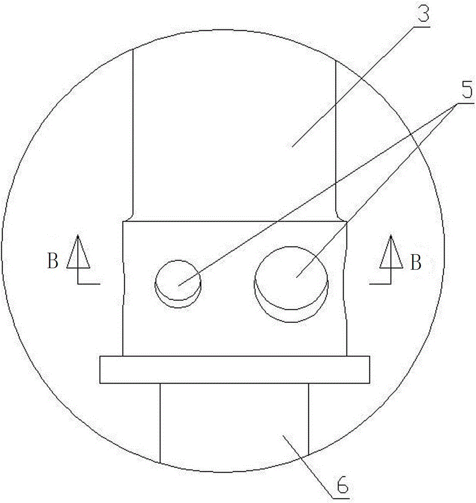
[0015] Such as Figure 1~Figure 4 As shown, the air distribution device for a biomass fluidized bed boiler of the present invention includes a bracket 1 on which a horizontally arranged air distribution plate 2 is arranged. There are no less than three air distribution boards 2, which are arranged side by side on the same horizontal straight line, and two adjacent air distribution boards 2 are connected together. The air distribution plate 2 is evenly processed with through holes, and the air distribution pipes 6 are fixed in the through holes. The wind cap 3 is evenly distributed with distribution air holes 5 around the wind cap 3 . The air distribution plate 2 is provided with a slag outlet 4 , and a slag outlet pipe 6 is connected to the lower end of the slag outlet 4 . The upper surface of the air distribution plate 2 is gradually lowered from the surr...


PUM


Abstract

The invention relates to a biomass fluidized-bed boiler assembly, and specifically relates to air distribution device for a biomass fluidized-bed boiler. The air distribution device comprises a support, wherein a horizontally-arranged air distribution plate is arranged on the support; through holes are uniformly distributed in the air distribution plate; an air distribution pipe is arranged in each through hole; the upper end of each air distribution pipe stretches out of the top of the air distribution plate; an air cap sleeves the upper end of each air distribution pipe; and air distribution holes are uniformly distributed in the periphery of each air cap. A slag outlet is formed in the air distribution plate, and a slag outlet pipe is connected to the lower end of the slag outlet. The air distribution device is characterized in that the upper surface of the air distribution plate is gradually descended from the peripheral edge to the periphery of the slag outlet, and thus an air distribution state that the periphery of a bed surface is inclined towards the slag outlet in the middle is formed. The fluidized-bed boiler using the air distribution device is high in working efficiency and low in maintenance cost.

Description

technical field [0001] The invention relates to a fluidized bed boiler assembly, in particular to an air distribution device for a biomass fluidized bed boiler, especially suitable for a biomass circulating fluidized bed. Background technique [0002] As we all know, air distribution devices need to be installed in fluidized bed boilers. A traditional air distribution device for a biomass fluidized bed boiler includes a bracket on which there is a horizontally arranged air distribution plate, which is in the shape of a flat plate. The air distribution plate is evenly distributed with through holes, and there are air distribution pipes in the through holes. The upper ends of the air distribution pipes all protrude from the top of the air distribution plate. Cloth has cloth air holes. There is a slag outlet on the air distribution plate, and a slag outlet pipe is connected to the lower end of the slag outlet. When working, the gas passes through the air pipe and the wind ca...

Claims


Application Information

Patent Timeline
Patent Type & Authority Applications(China)
IPC IPC(8): F23C10/20
CPCF23C10/20F23C2206/10
Inventor 高庆格宋金勇吴毅
Owner WUXI DONGMA BOILER
Learn More