
Rotary drum and drying machine comprising same

A rotary drum and dryer technology, applied in dryers, drying, sludge drying and other directions, can solve the problem of large heat loss and achieve the effects of less heat loss, stable structure, and stable and reliable connection

Inactive Publication Date: 2017-05-10
FOSHAN FENGHUI MACHINERY
View PDF7 Cites 4 Cited by
  • Summary
  • Abstract
  • Description
  • Claims
  • Application Information

AI Technical Summary

Problems solved by technology

In order to avoid damage to the shaft end bearing due to high temperature, a hollow shaft is usually selected for the rotating shaft, and circulating cooling water is introduced into the cavity of the rotating shaft to reduce the temperature of the rotating shaft and prolong the service life of the bearing. However, due to the cooling water, it will take away The heat in the rotary drum has a large loss of heat energy

Method used


Image

  • Rotary drum and drying machine comprising same
  • Rotary drum and drying machine comprising same
  • Rotary drum and drying machine comprising same

Examples


Embodiment 1

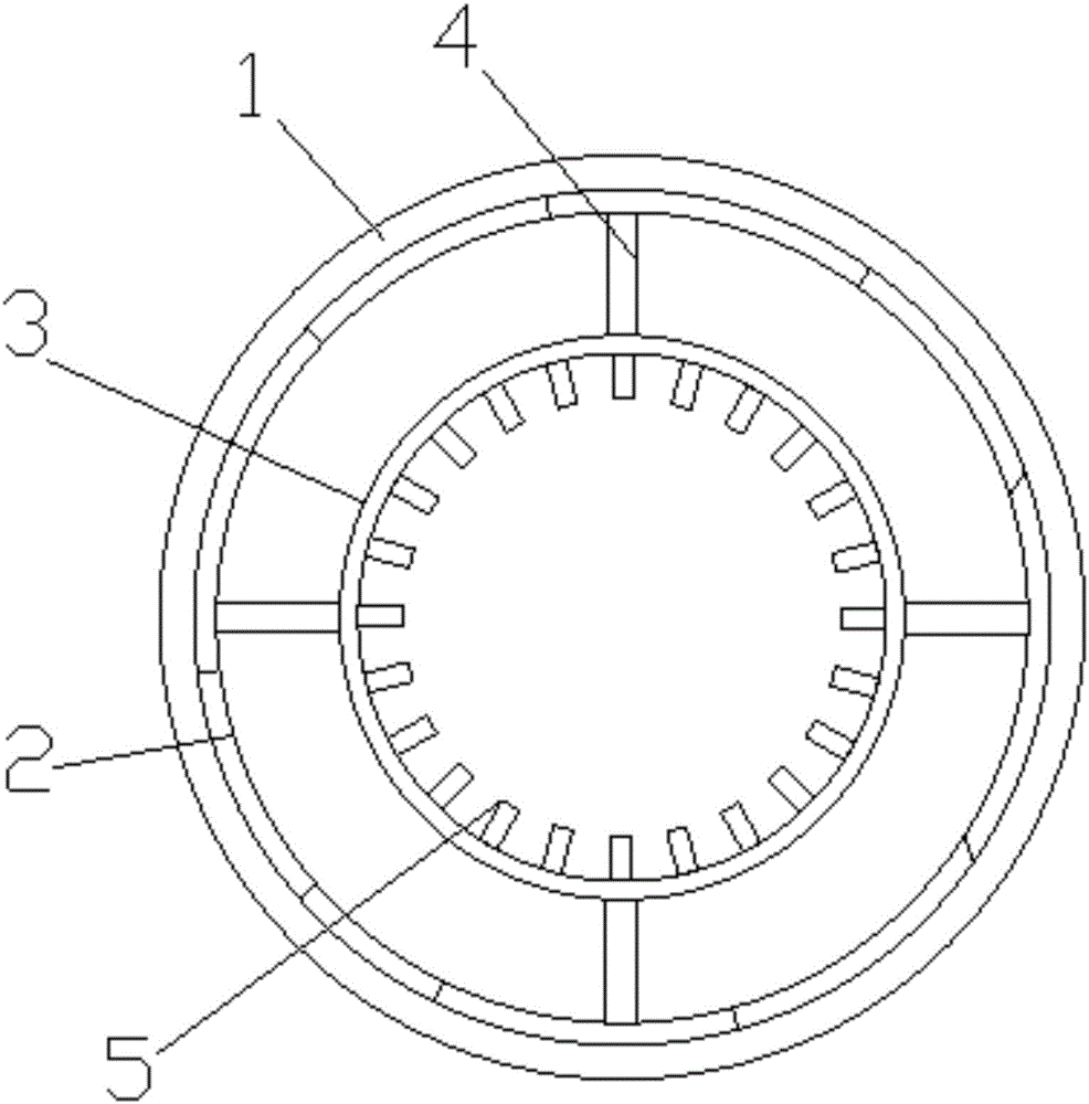
[0025] like figure 1 As shown, a rotary drum includes a rotary drum body 1 and a swirl plate 2, the swirl plate 2 is located on the inner surface of the rotary drum body 1 and is welded to the rotary drum body 1; the rotary drum body 1 A sieve 3 is arranged inside, and the sieve 3 is located at the same end as the feeding port of the rotary drum body 1. The rotary drum body 1 is fixedly connected with the sieve 3, and the sieve 3 operates synchronously with the rotary drum body 1. The sieve 3 is installed in the rotary cylinder body 1, compared with the traditional structure using a built-in mechanical dispersing device, since no cooling water is used, the loss of heat energy is small, and it will not be affected by the strength of the rotating shaft and the moment of inertia. Restrictions lead to the problem that the length of the breaking device and the length of the rotary drum cannot be designed too long.

[0026] The beneficial effects of the present invention are: the s...

Embodiment 2

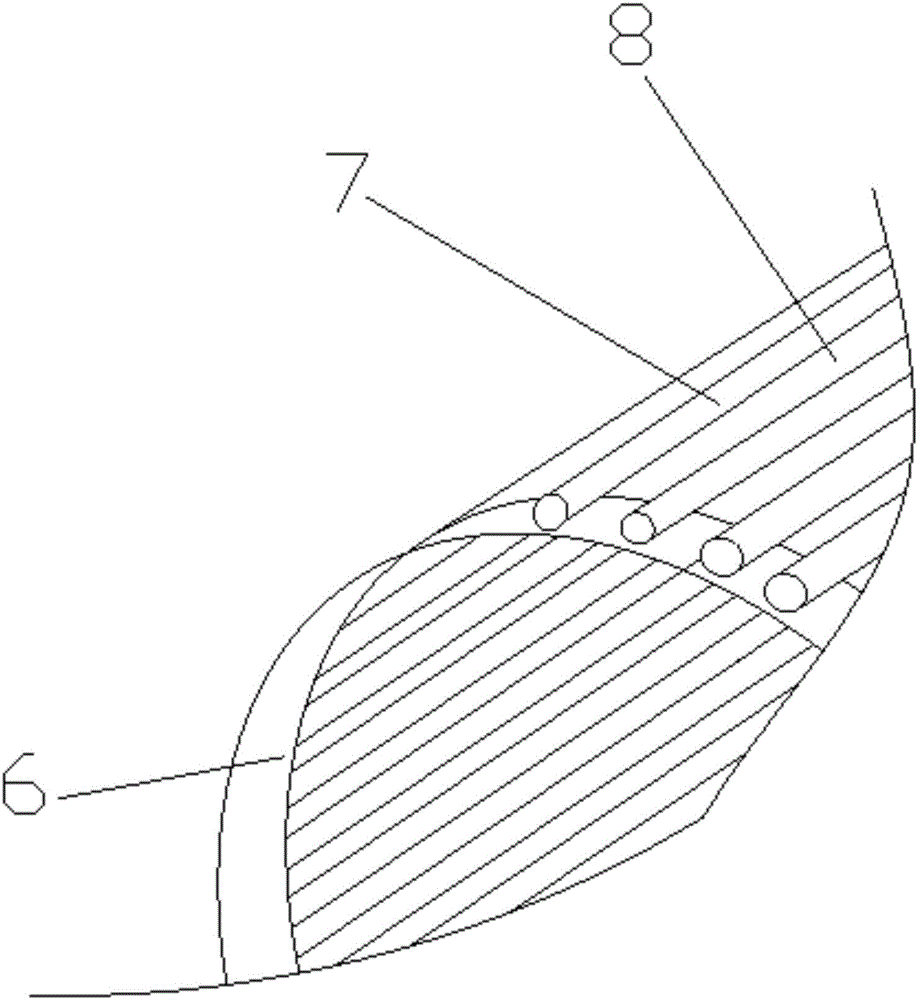
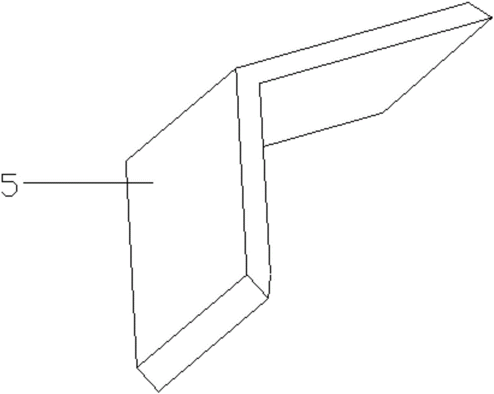
[0028] like Figure 1-3 As shown, a rotary drum includes a rotary drum body 1 and a swirl plate 2, the swirl plate 2 is located on the inner surface of the rotary drum body 1 and is welded to the rotary drum body 1; the rotary drum body 1 A sieve 3 is arranged inside, and the sieve 3 is located at the same end as the feeding port of the rotary cylinder body 1, and the rotary cylinder body 1 and the sieve 3 move in unison. A connecting frame 4 is arranged between the rotary drum body 1 and the sieve 3, and more than one connecting frame 4 is provided, and the connecting frame 4 is distributed in an annular array, and the rotary drum body 1 and the screen 3 are connected The connecting frame 4 is welded, and the rotary cylinder body 1 and the sieve 3 are connected through the connecting frame 4, so the structure is stable, and the connecting frame 4 is distributed in a circular array, which can effectively improve the stress stability of the sieve 3. The rotary cylinder body 1 ...


PUM


Abstract

The invention discloses a rotary drum. The rotary drum comprises a rotary drum body and a rotational flow plate; the rotational flow plate is located on the inner surface of the rotary drum body and is connected with the rotary drum body; a screen is arranged inside the rotary drum body; the screen and a feeding port of the rotary drum body are located at the same end; and the rotary drum body is linked with the screen. The rotary drum is low in heat loss.

Description

technical field [0001] The invention relates to a rotary drum and a rotary drum dryer. Background technique [0002] Dryers can be divided into industrial and civilian. Industrial dryers are also called drying equipment or dryers. Civilian dryers are one of washing machines. They are generally used to remove clothing and other textiles after washing and dehydration. of moisture. [0003] The dryer has several modes such as belt drying, rotary drum drying, box drying, tower drying, etc.; heat sources include coal, electricity, gas, etc.; the drying process of materials has hot air flow type and radiation type. wait. [0004] At present, the rotary drum of the rotary drum dryer generally adopts a built-in mechanical dispersing device, and the rotating shaft traverses the entire rotary drum along the axial direction of the rotary drum. Radial breaking teeth are installed along the radial direction of the rotating shaft. The two ends of the shaft are fixed and installed by b...

Claims


Application Information

Patent Timeline
Patent Type & Authority Applications(China)
IPC IPC(8): F26B17/34F26B25/04F26B25/16
CPCF26B17/34F26B25/04F26B25/16F26B2200/18
Inventor 孙亮黄文煜孙超郭光义
Owner FOSHAN FENGHUI MACHINERY
Learn More