A glass light guide plate and manufacturing method thereof
A technology for a glass light guide plate and a manufacturing method, which is applied in the field of light guide plates, can solve the problem of inability to form microstructures on the surface synchronously, and achieve the effects of eliminating the visual effect problem of Hotspot, reducing the amount of LEDs and improving the quality.
- Summary
- Abstract
- Description
- Claims
- Application Information
AI Technical Summary
Problems solved by technology
Method used
Image
Examples
Embodiment 1
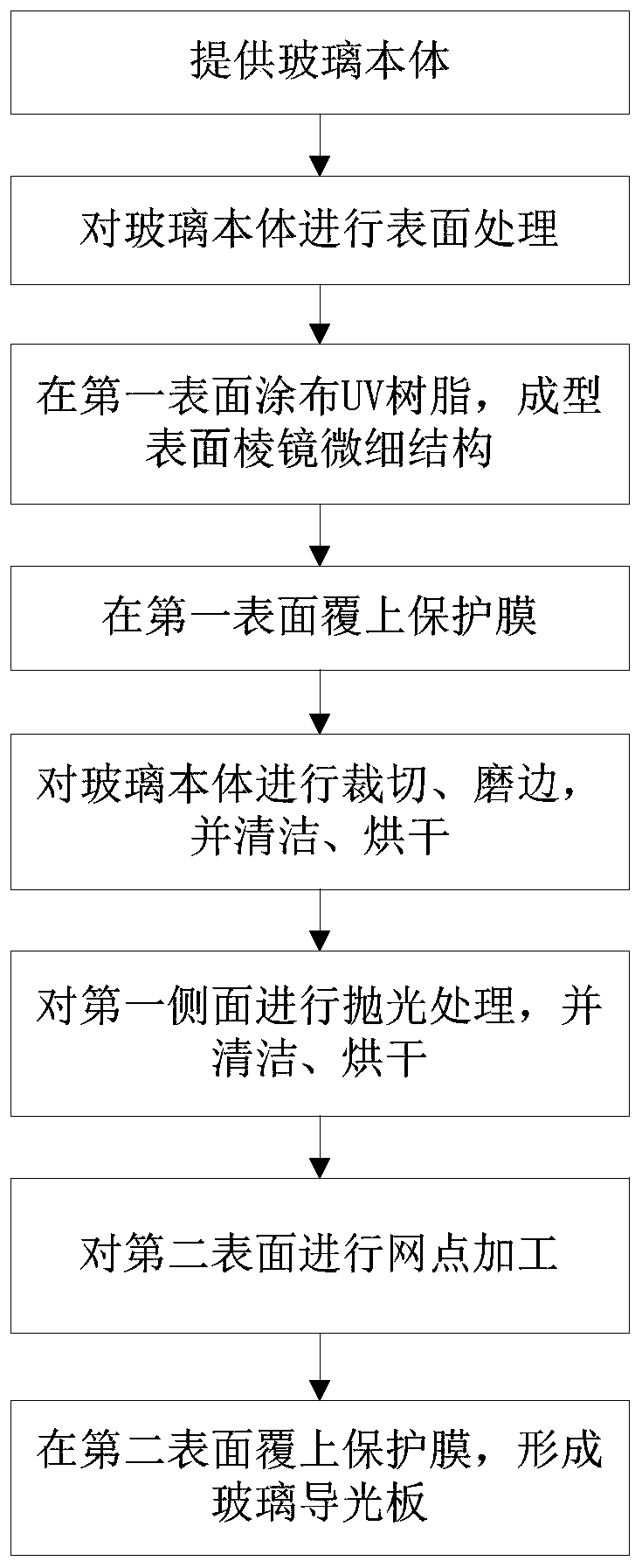
[0033] A method for manufacturing a glass light guide plate, comprising the steps of:
[0034] Step 1. Provide a glass body. The glass body has a first surface, a second surface opposite to the first surface, and a first side connecting the first surface and the second surface; preferably, the glass body is inorganic high-transmittance glass, which The refractive index is 1.49.
[0035] Step 2: Surface treatment is performed on the glass body; the surface treatment is ultrasonic chemical solvent cleaning, wherein the ultrasonic frequency is 50KHz, the ultrasonic time is 20min, and the ultrasonic temperature is 50°C. In this embodiment, a mixture of hydrofluoric acid is used, and according to the difference in solubility of the salts generated after the reaction between the glass body and the hydrofluoric acid mixture, the crystals remain on the surface of the glass body after the reaction to hinder further reaction between the hydrofluoric acid mixture and the glass body , so...
Embodiment 2
[0055] The difference between this embodiment and Embodiment 1 is only:
[0056] In step 2, the ultrasonic frequency is 60KHz, the ultrasonic time is 25min, and the ultrasonic temperature is 60°C.
[0057] In step 3, the thickness of the coating is 100 μm, the surface prism microstructure is a plurality of zigzag protrusions continuously arranged on the first surface, the height H of the protrusions is 65 μm, and the distance between two adjacent protrusions is P is 150 μm; the included angle C of the zigzag is 68°.
[0058] In the curing step after step three, the distance between the surface of the glass body and the UV lamp tube is 50mm, the baking time is 1min, and the baking energy is 1300MJ / cm 2 .
Embodiment 3
[0060] The difference between this embodiment and Embodiment 1 is only:
[0061] In step 2, the ultrasonic frequency is 70KHz, the ultrasonic time is 30min, and the ultrasonic temperature is 70°C;
[0062] In step 3, the thickness of the coating is 200 μm, the surface prism microstructure is a plurality of arc-shaped protrusions continuously arranged on the first surface, the height H of the protrusions is 100 μm, and the distance between two adjacent protrusions is The pitch P is 300 μm; the angle R of the arc shape is 158°.
[0063] In the curing step after step 3, the distance between the surface of the glass body and the UV lamp tube is 60mm, the baking time is 1.5min, and the baking energy is 1500MJ / cm 2 .
[0064] A glass light guide plate produced according to the above-mentioned production method, comprising a glass body, the glass body has a first surface and a second surface opposite to the first surface, the first surface is provided with a surface prism fine stru...
PUM
| Property | Measurement | Unit |
|---|---|---|
| thickness | aaaaa | aaaaa |
| height | aaaaa | aaaaa |
| thickness | aaaaa | aaaaa |
Abstract
Description
Claims
Application Information
 - R&D
- Intellectual Property
- Life Sciences
- Materials
- Tech Scout
- Unparalleled Data Quality
- Higher Quality Content
- 60% Fewer Hallucinations
Browse by: Latest US Patents, China's latest patents, Technical Efficacy Thesaurus, Application Domain, Technology Topic, Popular Technical Reports.
© 2025 PatSnap. All rights reserved.Legal|Privacy policy|Modern Slavery Act Transparency Statement|Sitemap|About US| Contact US: help@patsnap.com


