Light guide plate and back light unit employing the same

A backlight module and light source technology, applied in optics, nonlinear optics, instruments, etc., can solve problems such as difficulty in controlling the brightness uniformity of the backlight module 1

Inactive Publication Date: 2008-11-12
AU OPTRONICS CORP
View PDF7 Cites 0 Cited by
  • Summary
  • Abstract
  • Description
  • Claims
  • Application Information

AI Technical Summary

Problems solved by technology

However, also due to the existence of the optical film 17, it is difficult to control the overall brightness uniformity of the backlight module 1

Method used


Image

  • Light guide plate and back light unit employing the same
  • Light guide plate and back light unit employing the same
  • Light guide plate and back light unit employing the same

Examples


Embodiment Construction

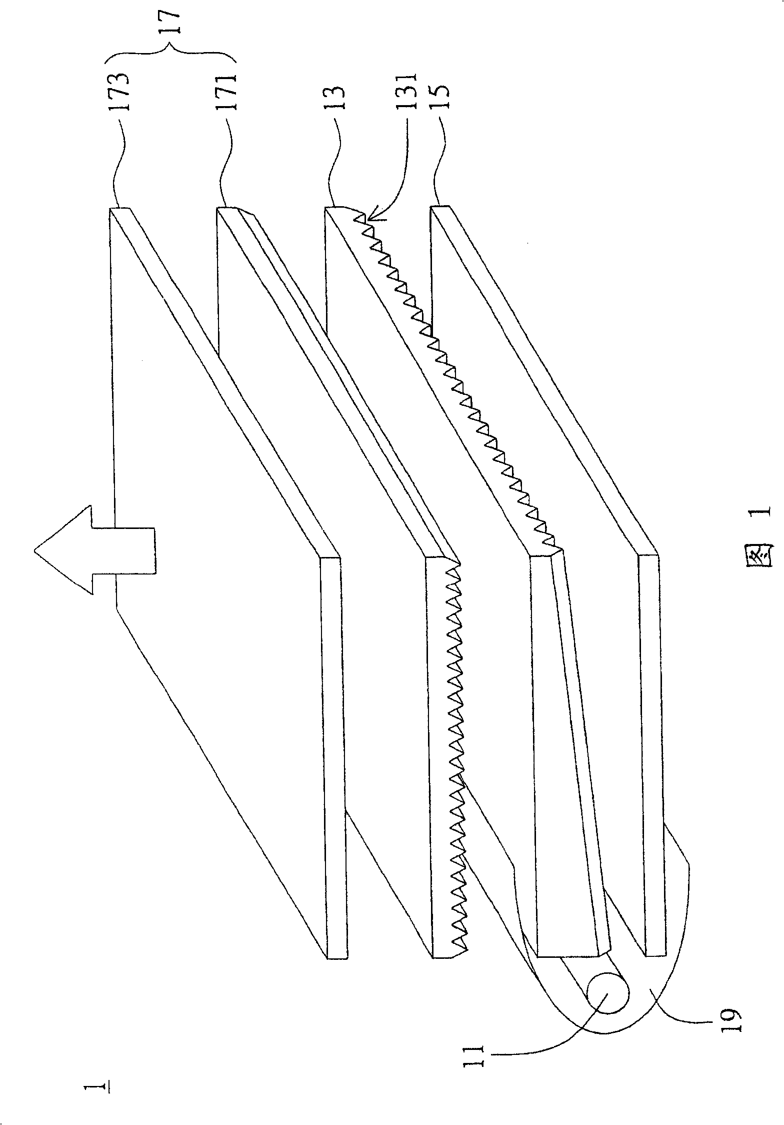
[0040] The present invention proposes a light guide plate, which is applied to the backlight module of a liquid crystal display device, mainly to form a special optical structure design (or a gradient prism structure design) on the light guide plate to improve the overall optical brightness of the backlight module, especially Optical brightness in a small viewing angle range. The following is a detailed description of the present invention with a preferred embodiment, however, this embodiment will not limit the protection scope of the present invention. In addition, unnecessary elements are omitted in the diagrams to clearly show the technical characteristics of the present invention.

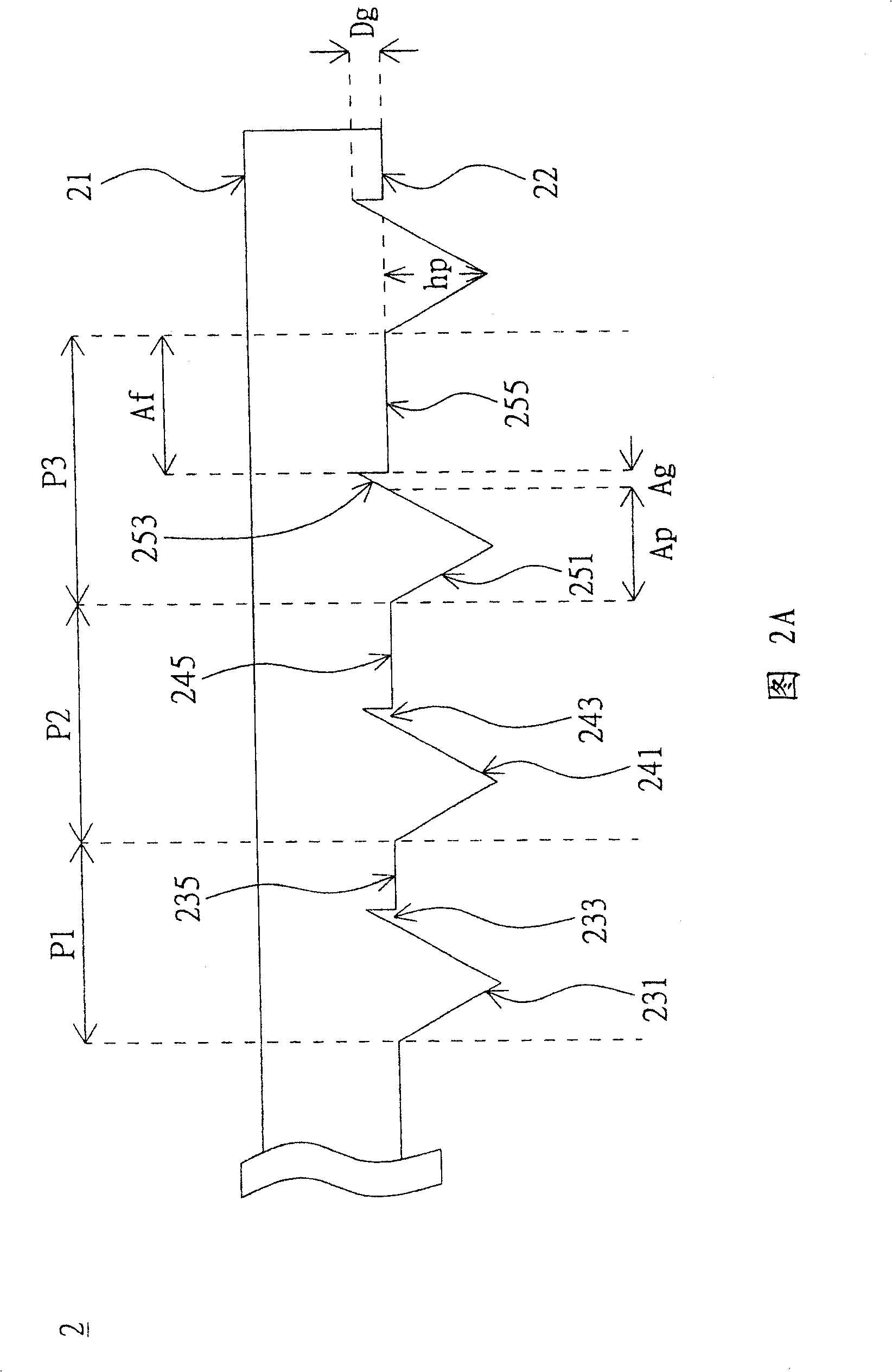
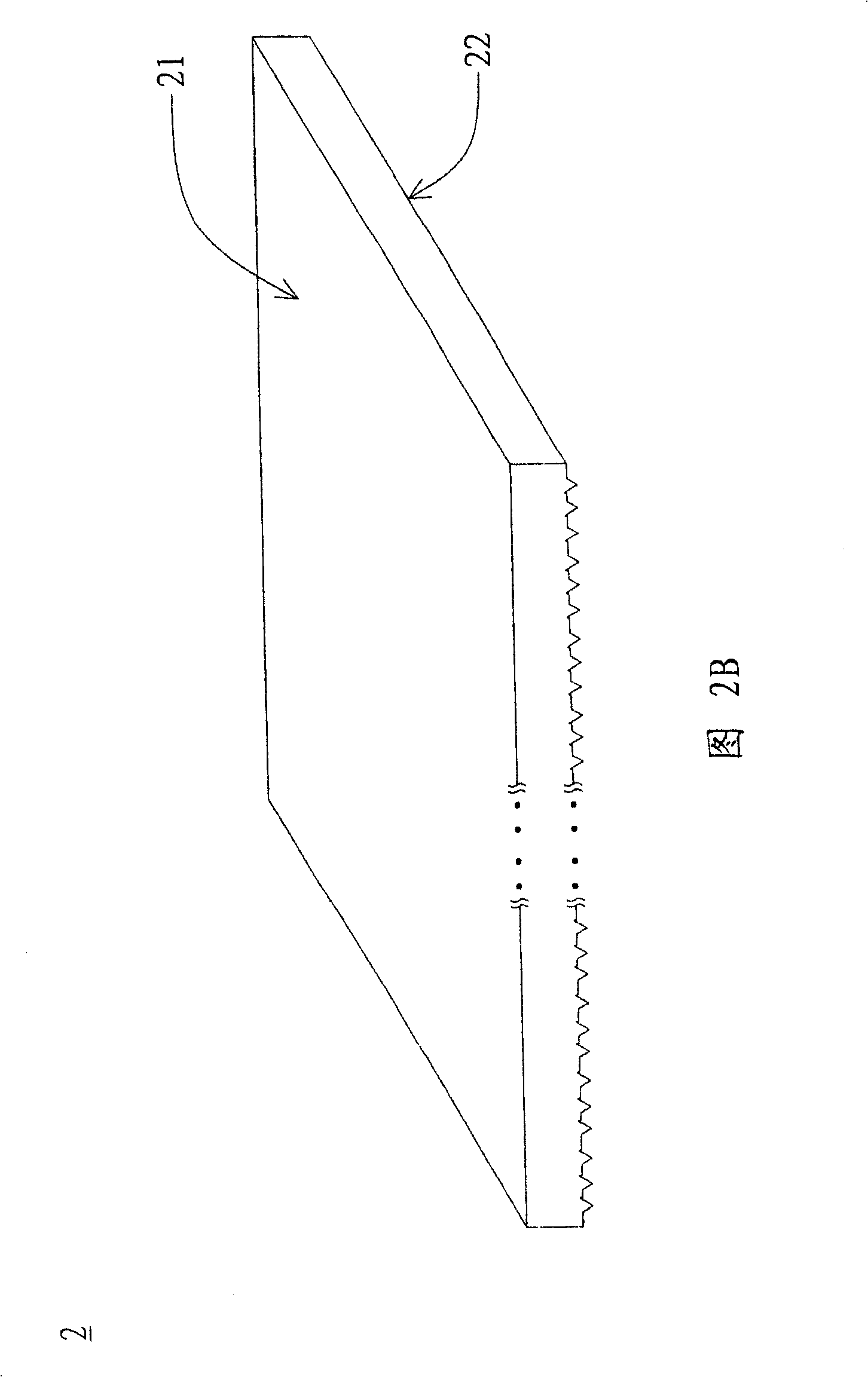
[0041] Please refer to FIG. 2A and FIG. 2B , which illustrate a schematic cross-sectional view and a perspective view of a first-type light guide plate according to a preferred embodiment of the present invention. As shown in FIG. 2A , a light guide plate (LGP) 2 includes a first surface 21 an...


PUM


Abstract

This invention relates to a light guide plate and back light unit employing the same, which comprises a first surface and an opposite second surface. Wherein, the second surface comprises a plurality of optical structures every with a projecting portion, a groove portion, a projecting connection, and a flat portion with one end connected to the grooving portion. Besides, the pitches of these optical structures are different.

Description

technical field [0001] The present invention relates to a light guide plate and a backlight module applied thereto, in particular to a light guide plate capable of effectively improving the brightness in a small viewing angle range of a liquid crystal display device and a backlight module applied thereto. Background technique [0002] Liquid crystal display devices that can produce rich and bright graphics are widely used in portable information products such as notebook computers and personal digital assistants due to their thin and light appearance, low power consumption, and no radiation pollution, and are even gradually replacing The cathode ray tube (Cathode Ray Tube, CRT) monitor traditionally used in desktop computers. [0003] The liquid crystal display device is mainly composed of a display unit, a backlight module and a casing with a frame. The display unit includes a display panel, a circuit board capable of processing data signals, and a supporting thin film pac...

Claims


Application Information

Patent Timeline
Patent Type & Authority Patents(China)
IPC IPC(8): G02F1/13357G02F1/1335
Inventor 高克嘉廖经桓陈志光黄志濠
Owner AU OPTRONICS CORP
Why Eureka
Try Eureka